Dynamic hand splints

a hand splint and dynamic technology, applied in the field of hands, can solve the problems of inability to extend the wrist or fingers to grasp objects, and achieve the effect of preventing distal migration and providing different resistances to the flexing of fingers

Active Publication Date: 2006-09-21
SAEBO
View PDF26 Cites 65 Cited by
  • Summary
  • Abstract
  • Description
  • Claims
  • Application Information

AI Technical Summary

Benefits of technology

[0017] In another feature of the invention, the forearm support section includes an interior surface comprising a removable padded lining. The lining further may include a non-skid material in order to prevent distal migration of said forearm support section. The same or a similar non-skid material may be included on the volar sides of digit sleeves and / or on a palm covering to assist in gripping of an object by the hand using the dynamic hand splint.
[0018] In still yet another feature, the hand support section includes, on a dorsal side thereof, quick-release attachment sites for changing of the finger tensioners releasably attached to the hand support section. By changing of the finger tensioners, differing resistances to the flexing of the fingers can readily and easily be provided.

Problems solved by technology

Many have some shoulder and elbow movements, but are unable to extend their wrist or fingers to grasp an object.

Method used


Image

  • Dynamic hand splints
  • Dynamic hand splints
  • Dynamic hand splints

Examples


first embodiment

The First Embodiment

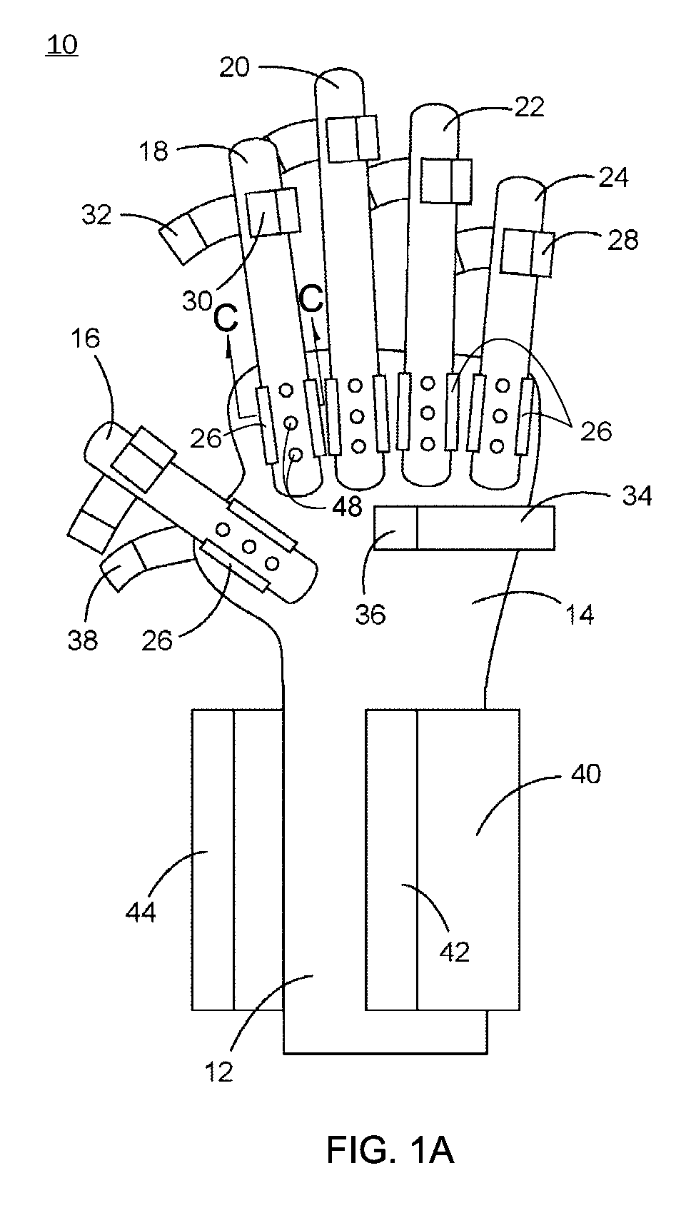
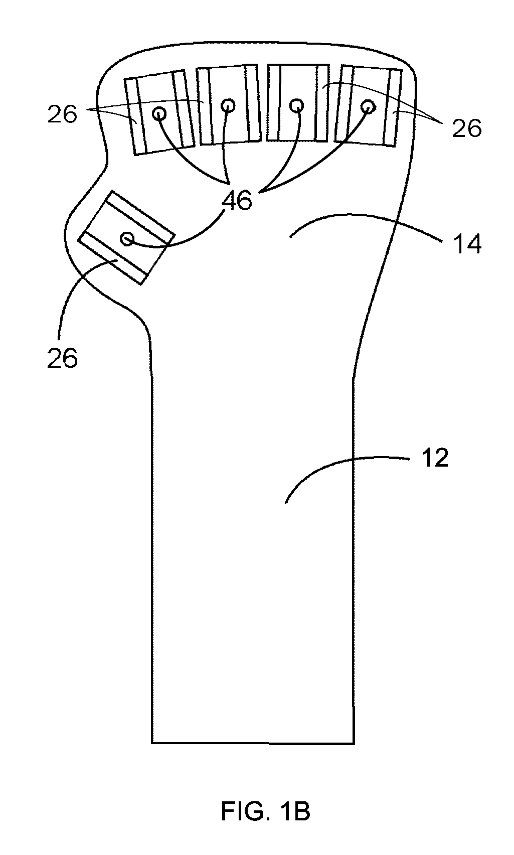
[0059] A dynamic hand splint 10 in accordance with a first preferred embodiment of the present invention is illustrated in FIGS. 1A-1C. The splint 10 includes a forearm support section 12 and a hand support section 14. As shown, the forearm support section 12 and the hand support section 14 (including both the portions, described below, that are related to the fingers and to the thumb) are integrally formed and together constitute a component of the dynamic hand splint. Alternatively, however, the forearm support section 12 and the hand support section 14 are not integral but, instead, are attached together directly or indirectly through an intermediate connector such as hook-and-loop fasteners (of which the second and third embodiments disclosed below are exemplary). Also alternatively, the portion of the hand support section 14 that is related to the fingers and the portion of the hand support section 14 that is related to the thumb are not integral but, instea...

second embodiment

The Second Embodiment

[0077] A dynamic hand splint 20 in accordance with a second preferred embodiment of the present invention is illustrated in FIGS. 2A and 2B. As with the splint 10 of FIGS. 1A-1C, this second splint 20 includes a forearm support section 112 and a hand support section 114. Unlike the forearm support section 12 and the hand support section 14 of the splint 10 of the first embodiment, however, the forearm support section 112 and the hand support section 114 of the splint 20 of the second embodiment are not integrally formed but, instead, comprise two separate components of the dynamic hand splint 20. As such, the forearm support section 112 may be separately donned prior to donning of the hand support section 114.

[0078] The forearm support section 112 of the splint 20 of the second embodiment is preferably flexible and may be constructed from any suitable plastic, metal, or alloy material. The forearm support section 112 also preferably is configured and dimensione...

third embodiment

The Third Embodiment

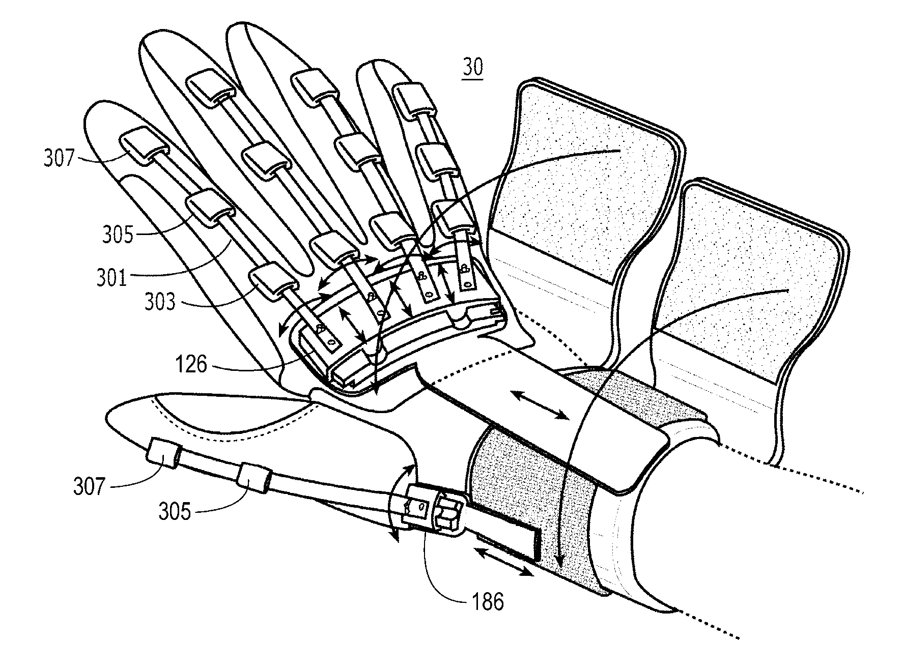
[0104] A dynamic hand splint 30 in accordance with a third preferred embodiment of the present invention is illustrated in FIGS. 3A and 3B and is generally similar in design to the second hand splint 20 of FIGS. 2A and 2B. Due to the similarity, and in the interests of brevity, only differences in the designs of the second and third illustrated embodiments of the dynamic hand splints 20,30 will be described.

[0105] In this regard, the principle difference in design relates to the finger and thumb tensioners and attachment of the finger and thumb tensioners to the sleeves 128,188. Specifically, whereas the tensioners in the second embodiment of the hand splint 20 comprise resilient struts 116,118,120,122,124 such as, for example, strips of spring steel or composite rods, that are secured to the sleeves 128,188 by pockets 130,190, the tensioners of the hand splint 30 of the third embodiment may be thinner and may comprise resilient bands 301 that are secured to the...


PUM


Abstract

A dynamic hand splint includes as elements thereof: a forearm support section and a hand support section that are configured to be releasably attached to a forearm; and one or more finger tensioners that are releasably attached to the hand support section and that are configured to be releasably attached to a respective finger such that, when the finger is flexed from an extended position toward a flexed position, the finger is urged by the finger tensioner toward an extended position. A method includes: attaching a forearm support section and a hand support section to a forearm; attaching finger tensioners to the hand support section; and attaching each of the finger tensioners to a respective finger such that, when the finger is flexed from an extended position toward a flexed position, the finger is urged by the finger tensioner toward an extended position.

Description

CROSS-REFERENCE TO RELATED APPLICATIONS [0001] The present application is a nonprovisional patent application of, and claims priority under 35 U.S.C. § 119(e) to, U.S. provisional patent application Ser. No. 60 / 635,332, filed Dec. 10, 2004, which provisional patent application is incorporated by reference herein.COPYRIGHT STATEMENT [0002] All of the material in this patent document is subject to copyright protection under the copyright laws of the United States and other countries. The copyright owner has no objection to the facsimile reproduction by anyone of the patent document or the patent disclosure, as it appears in official governmental records but, otherwise, all other copyright rights whatsoever are reserved. FIELD OF THE INVENTION [0003] The present invention generally relates to orthoses and, in particular, to dynamic hand splints. BACKGROUND OF THE INVENTION [0004] Many people suffering a neurological injury from stroke, cerebral palsy, brain injury, etc., have upper ext...

Claims


Application Information

Patent Timeline
Patent Type & Authority Applications(United States)
IPC IPC(8): A61F5/00
CPCA61F5/0118A61F5/05866A61F2005/0179
Inventor FARRELL, JOHN FLETCHERHOFFMAN, HENRY B.
Owner SAEBO
Why Eureka
Try Eureka