Base coupling structure of a height adjustable chair

Inactive Publication Date: 2006-09-28
CHENG HSIEN YAN
View PDF5 Cites 11 Cited by
  • Summary
  • Abstract
  • Description
  • Claims
  • Application Information

AI Technical Summary

Benefits of technology

[0004] It is a primary object of the present invention is to provide a coupling structure for the oil cylinder and the foot support o

Problems solved by technology

Although the altitude of the seat portion 1 of the conventional height adjustable chair can be adjusted according to the demand of the user, the oil cylinder 2 of the conventional height adjustable chair is easily damaged by the over frequent adjustment.
Therefore, the fo

Method used


Image

  • Base coupling structure of a height adjustable chair
  • Base coupling structure of a height adjustable chair
  • Base coupling structure of a height adjustable chair

Examples


Example

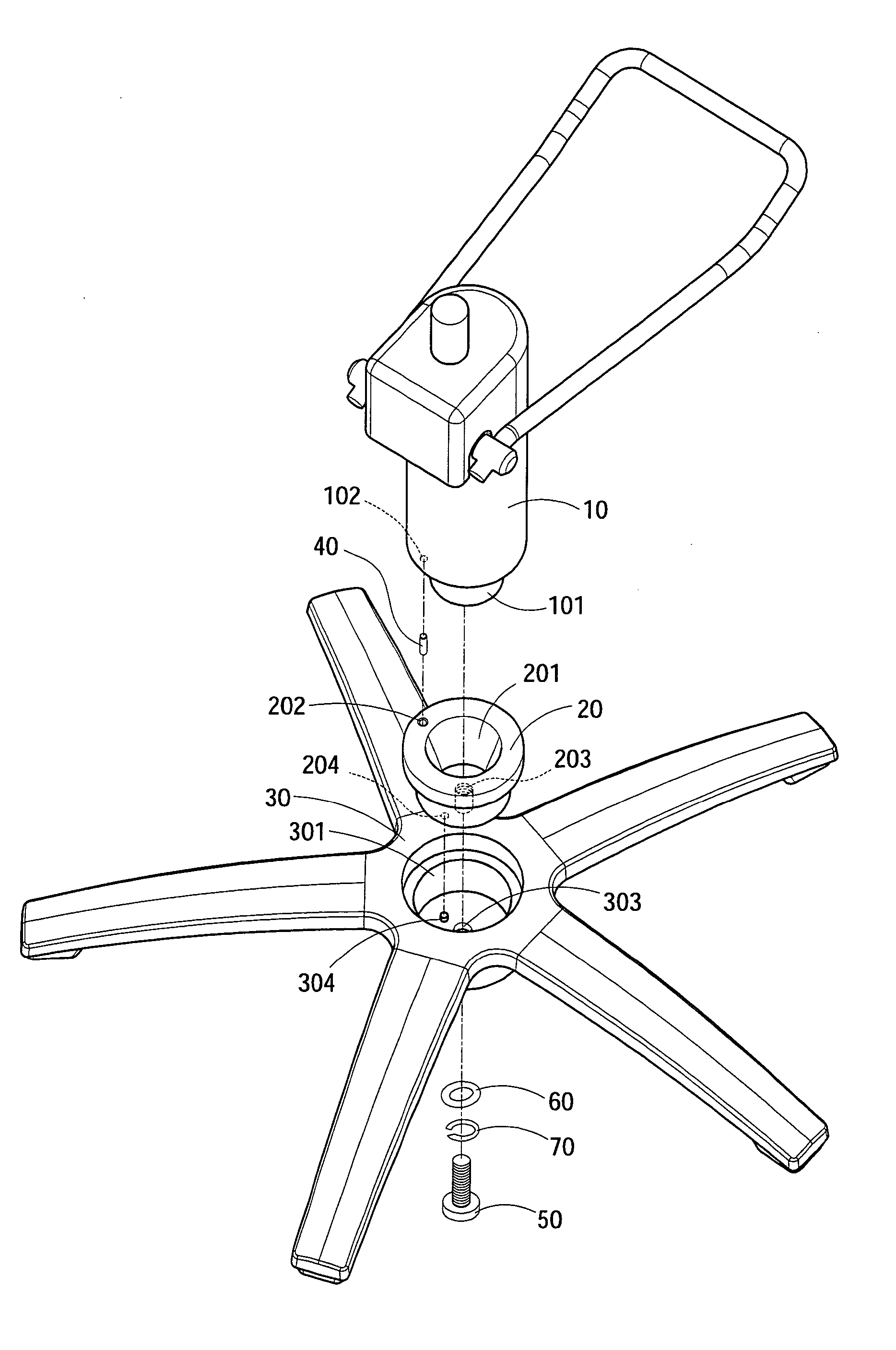
[0013] Please refer to FIGS. 3 and 4. The base coupling structure of a height adjustable chair of the present invention comprises an oil cylinder 10, a sleeve 20 and a foot support 30. The bottom of the oil cylinder 10 has a connecting post 101 and such connecting post 101 has a taper. The sleeve 20 having a receiving hole 201 which has a larger outer circumference and a smaller inner circumference. And the size of the receiving hole 201 corresponds to the size of the connecting post 101 of the oil cylinder 10, so that the largest aperture of the receiving hole 201 is slightly bigger than the connecting post 101 and the smallest aperture of the receiving hole 201 is slightly smaller than the connecting post 101. Thus, the connecting post 101 of the oil cylinder 10 can be tightly embedded into the receiving hole 201 of the sleeve 20 by taking the advantages of having slightly different taper sizes and different elasticity of materials. The oil cylinder 10 can be tightly embedded with...


PUM


Abstract

A base coupling structure of a height adjustable chair, using a sleeve to connect an oil cylinder and a foot support of a height adjustable chair, the sleeve and the oil cylinder can be tightly embedded together by taking the advantages of having slightly different taper sizes and different elasticity of materials, and the sleeve is coupled with the foot support by a screwing base structure which can be dismantle, so the present invention not only can enhance the speed of the replacing the used oil cylinder, but also can protect the foot support from being damaged and allow a reduction in service cost of the height adjustable chair.

Description

FIELD OF THE INVENTION [0001] The present invention relates to a base structure of a height adjustable chair and, more particularly, to a coupling structure between an oil cylinder and a foot support of the base of a height adjustable chair. BACKGROUND OF THE INVENTION [0002] Please refer to FIGS. 1 and 2, the conventional height adjustable chair comprises of a seat portion 1, an oil cylinder 2 and a foot support 3. The oil cylinder 2 includes an adjustable lever 2c, an extensible rod 2a and a connecting post 2b. The extensible rod 2a is mounted underneath the seat portion 1 by a suited base 4 and a plurality of screws 5. Both the connecting post 2b and the foot support 3 having a taper correspondingly, so that the connecting post 2b can be tightly embedded into the foot support 3 by the slightly differences between the taper sizes and the elasticity of the materials between the two. According to the above structure, users can activate the adjustable lever 2c to elongate the extensi...

Claims


Application Information

Patent Timeline
IPC IPC(8): A47C1/00
CPCA47C3/30
Inventor CHENG, HSIEN-YAN
Owner CHENG HSIEN YAN
Why Eureka
Try Eureka