Pointing device for large field of view displays

a display and large field of view technology, applied in computing, instruments, electric digital data processing, etc., can solve the problems of user making multiple mouse or other input device movements to move the cursor from one area of the display to another area of the display, and it is difficult to establish a single control-display ratio, etc., to achieve the effect of improving the positioning of the cursor

Inactive Publication Date: 2006-09-28
EASTMAN KODAK CO
View PDF13 Cites 39 Cited by
  • Summary
  • Abstract
  • Description
  • Claims
  • Application Information

AI Technical Summary

Benefits of technology

[0011] The present invention is directed to an interactive system for improving cursor positioning on a display comprising a screen or series of screens having a field of view of greater than 30 degrees with respect to a user, wherein the system includes: a user controlled input device for positioning a cursor on the display; a means for

Problems solved by technology

Even with relatively small display surfaces, such as the 17 to 19 inch displays that are commonly used today, it is difficult to establish a single control-display ratio that allows both the resolution of control necessary to select items in today's operating systems and yet allow the user to quickly move the cursor the entire diagonal of the display device.
However, as the display surface becomes larger it becomes more difficult to simply adjust the control-display ratio to accommodate both the fine control required for selection and still allow the cursor to be moved with a small movement from the bottom right to the top right of a display.
It is worth noting that requiring the user to make multiple mouse or other input device movements to move the cursor from one area of a display to another area of the display is undesirable for at least two reasons.
The first of these is the simple loss of productivity that occurs since the user spends more time making multiple movements to move the cursor from one side to the other of the display.
The second of these is an increase in repetitive motions that will increase the potential for increased biomechanical stress and may lead to a further increased incidence of repetitive motion disorders, such as carpal tunnel syndrome.
Unfortunately, these input techniques generally do not provide a mechanism for fine control of a cursor.
While the method proposed by Amir et al. accomplishes the task of determining the user's attention, potentially eliminating the need for large mouse movements, this method has a number of sign

Method used


Image

  • Pointing device for large field of view displays
  • Pointing device for large field of view displays
  • Pointing device for large field of view displays

Examples


Embodiment Construction

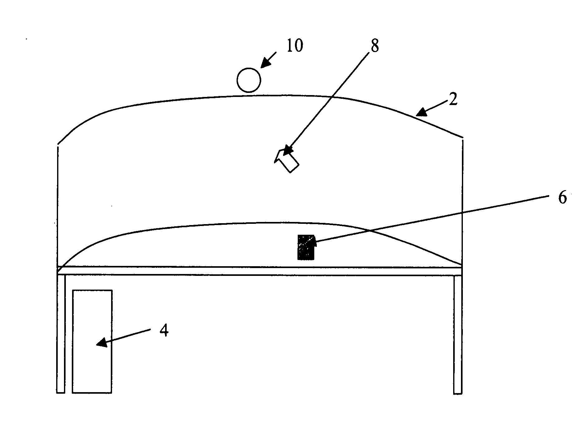
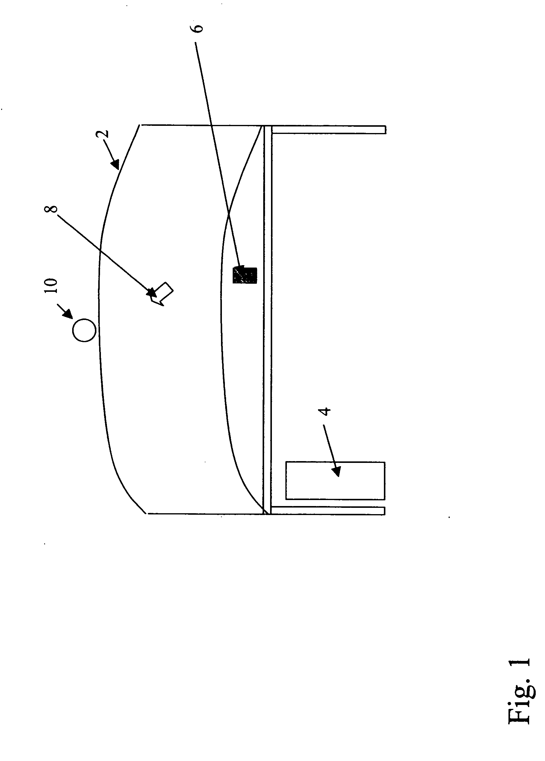
[0015] This invention takes advantage of the fact that a human operator generally moves his or her head in concert with eye movements whenever significant shifts in attention occur in order to provide improved cursor positioning. As described by A. R. Tilley in the book entitled “The Measure of Man and Women” published by Henry Dreyfuss Associates, New York, 1993, users generally find eye rotation to plus or minus 15 degrees off center to be easy. The user will make larger eye movements, however, head movements will typically accompany these eye movements. Eye movements beyond plus or minus 35 degrees can not be made, requiring that the user rotate his or her head to gather visual information. It is generally more comfortable for a user to maintain their eyes pointed straight ahead than to look to the side. For this reason, the user may make head movements even when eye movements of 15 degrees or less are required.

[0016] The fact that eye movements, especially those beyond plus or ...


PUM


Abstract

An interactive system for improving cursor positioning on a display comprising a screen or series of screens having a field of view of greater than 30 degrees with respect to a user, wherein the system includes: a user controlled input device for positioning a cursor on the display; a means for determining the relative location and orientation of the user's head with respect to the display; and a cursor repositioning means for determining an implied region of interest on the display based on the relative location and orientation of the user's head and moving the cursor to a selected position within the implied region of interest.

Description

FIELD OF THE INVENTION [0001] The present invention relates to computer human user interface. Particularly, the invention provides an enhanced pointing device behavior for computer workstations having large field of view displays. BACKGROUND OF THE INVENTION [0002] Pointing devices, including mice, trackpads, trackballs and other devices, such as the IBM TrackPoint; currently provide the preferred method for a human to control the position of a cursor within a graphical computer interface. These devices have been optimized to provide the ability to select small regions, such as a checkbox, within a computer interface while also allowing the user to quickly move the cursor quickly across a display surface. To allow both functions, the control-display ratio of these devices has been finely tuned to allow both fine motor control required for object selection and quick cursor movement required to quickly move the cursor across the display. The control-display ratio is the ratio of the d...

Claims


Application Information

Patent Timeline
IPC IPC(8): G09G5/08
CPCG06F3/012G06F3/033G06F3/038
Inventor MILLER, MICHAEL E.
Owner EASTMAN KODAK CO
Why Eureka
Try Eureka