Swimming goggles

Active Publication Date: 2006-10-05
CHIANG HERMAN
9 Cites 18 Cited by

AI-Extracted Technical Summary

Problems solved by technology

However, the frame 90 is not flexible enough to bend inwardly owing to hard upper portion 902 of the frame 90.
Correspondingly, users, who have small face profiles, will feel uncomfortable due to un...

Benefits of technology

[0006] Accordingly, an object of the present invention is to provide swimming goggles which serve users well and prevent from water leakage as wearing. The swimming goggles comprise a frame which has flexib...

Abstract

Swimming goggles comprise a frame, eyeglasses, a pad and compressing devices. The eyeglasses are received in the pad, and the compressing devices are mounted on opposite outer sides of the frame for compressing the eyeglasses and the pad, wherein each compressing device includes a first cover and a second cover which are assembled together and receive a head strip. The frame has an upper frame, a lower frame and a nose support. Cracks are defined on both sides of the upper frame and the lower frame. The upper frame forms a gap in a middle of an inner edge thereof for making the frame flexible to bend inwardly thereby fitting for various users who have different face profiles.

Application Domain

GogglesSwim goggles +2

Technology Topic

EngineeringEyewear +2

Image

  • Swimming goggles
  • Swimming goggles
  • Swimming goggles

Examples

  • Experimental program(1)

Example

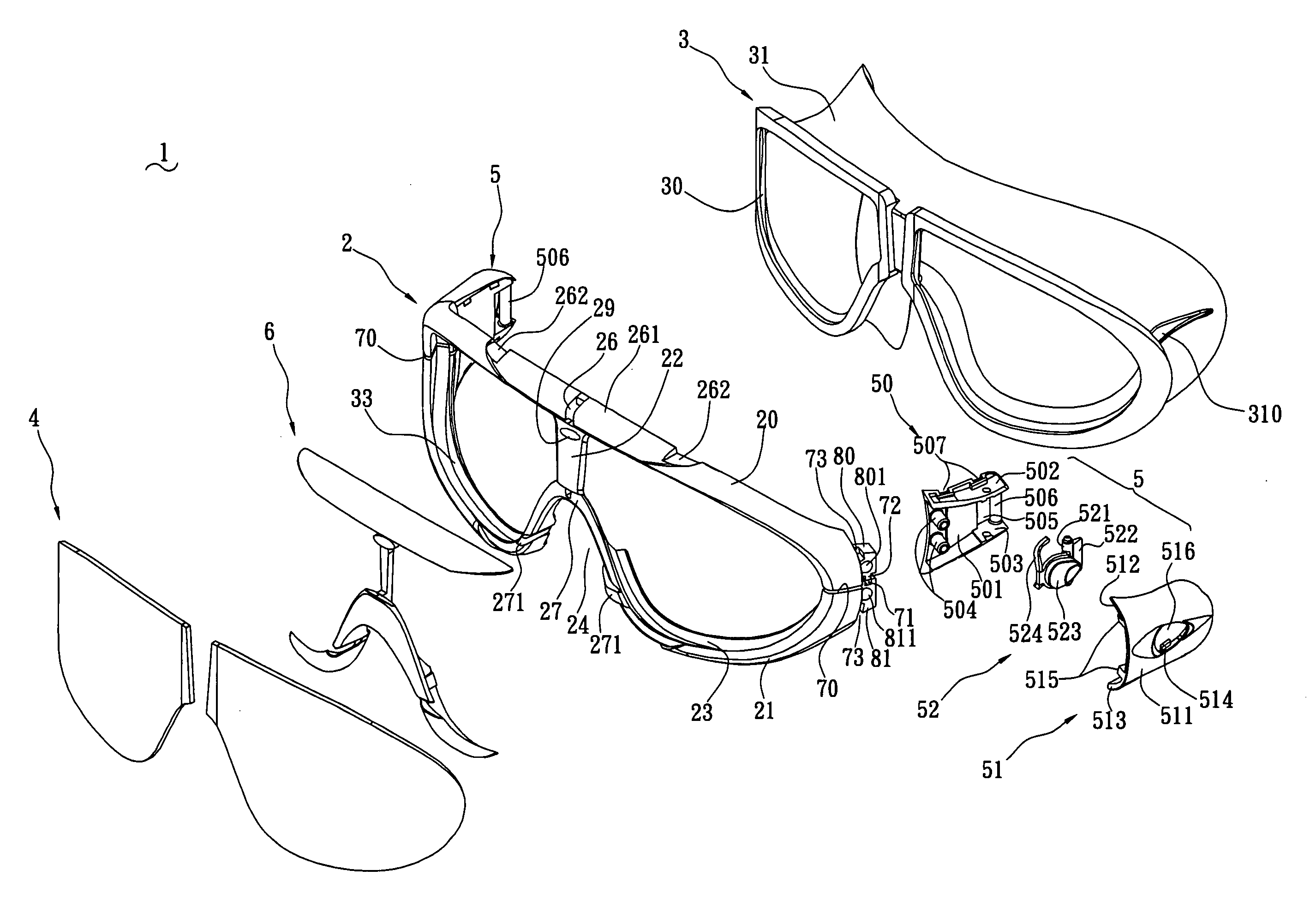
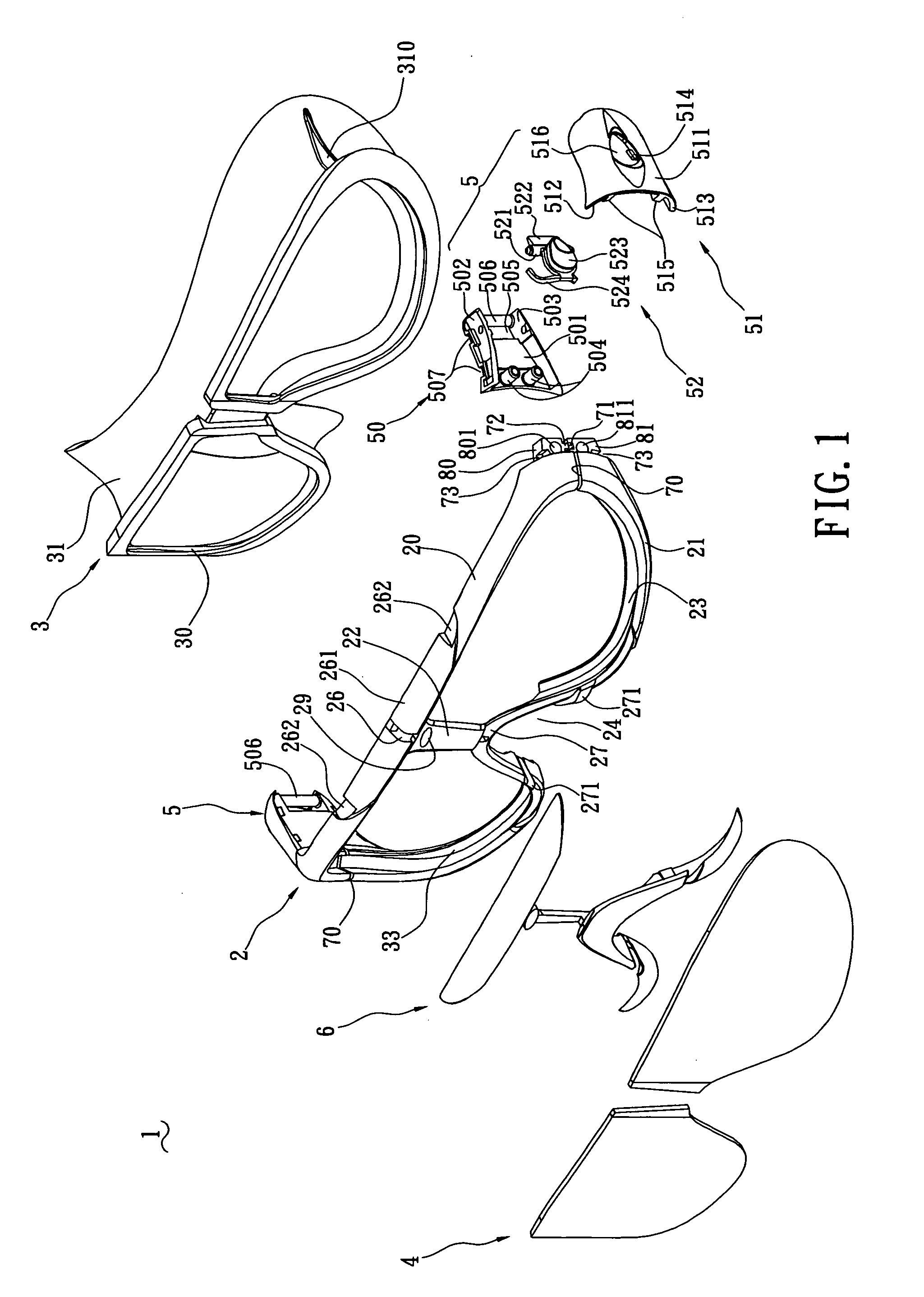
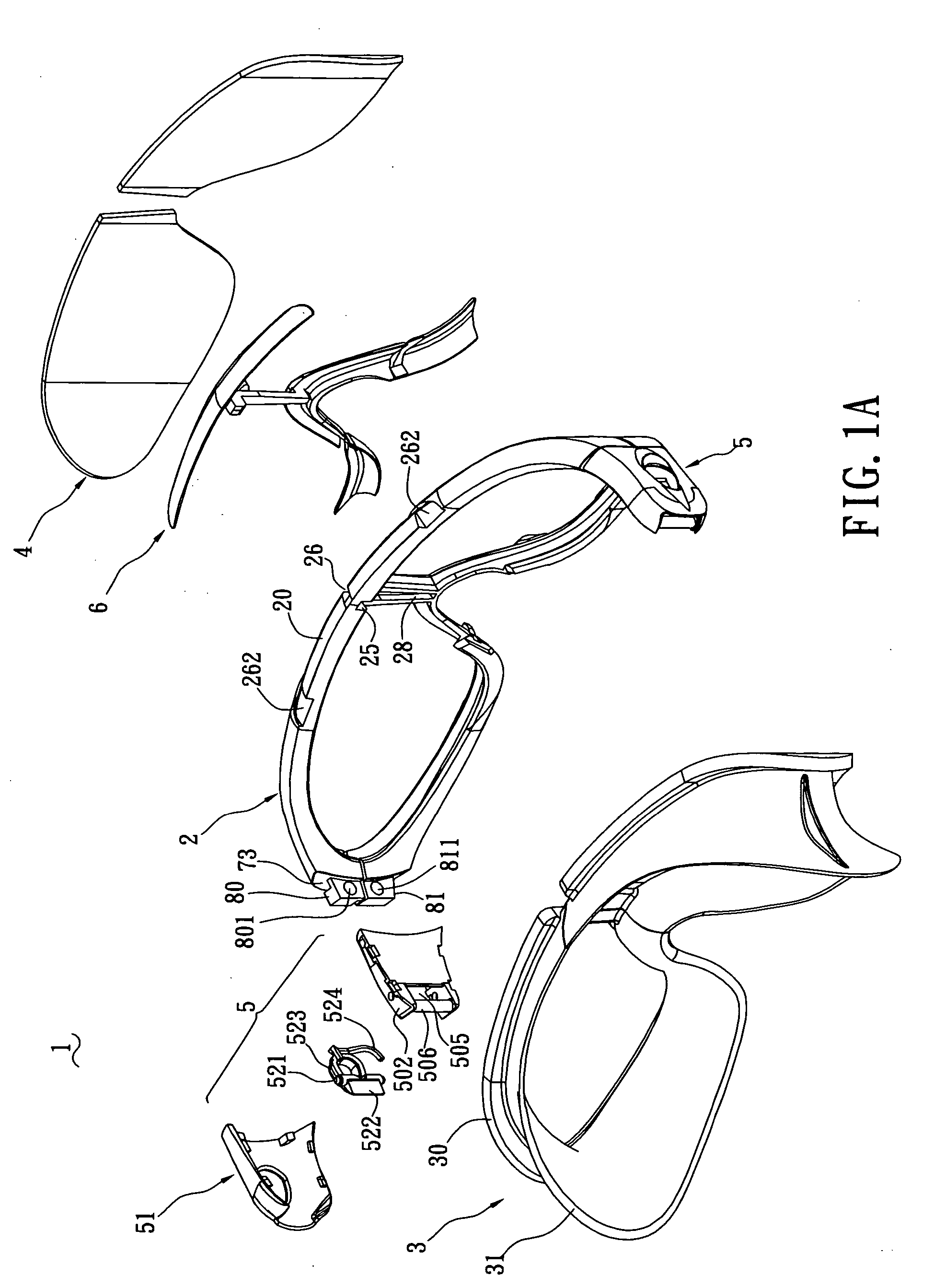
[0015] With reference to FIG. 1, swimming goggles 1 of the present invention comprise a frame 2, a pad 3, two eyeglasses 4 and compressing devices 5. The frame 2 has an upper frame 20, a lower frame 21 and a nose support 22. The upper frame 20 and the lower frame 21 define closed space for accommodating the eyeglasses 4. Receiving grooves 23 are respectively defined along inner edges of the upper frame 20 and the lower frame 21 for receiving the pad 3. The nose support 22 is arranged on a middle of the upper frame 20, and connects the upper frame 20 and the lower frame 21 thereby dividing the closed space into two slots (not labeled) respectively for accommodating the eyeglasses 4. The lower frame 21 forms a concave portion 24 for straddling a user's nose. The upper frame 20 forms a gap 25 (shown in FIG. 1A) in a middle of an inner edge thereof, and forms an inject hole 26 communicating with the gap 25. Camber portions 261 are slightly concave respectively on both sides of the inject hole 26. Engaging grooves 262 are respectively formed on both sides of the camber portions 261, whereby the soft frame 6 covers the inject hole 26 and the camber portions 261 and clamps the engaging grooves 262. The lower frame 21 has an enveloping surface 27 about the concave portions 24. Similarly, the enveloping surface 27 is shrouded by the soft frame 6, whereby the portions about the concave portions 24 are of comfortable touch. Barbs 271 are provided on the enveloping surface 27 for retaining the soft frame 6. Further referring to FIG. 4, an enveloping groove 28 is defined in the nose support 22 and communicates with the gap 25. A mark hole 29 is defined in the nose support 22 and communicates with the enveloping groove 28. The mark hole 29 may be shaped as characters or pictures of a brand mark. The soft frame 6 also shrouds the enveloping groove 28 and the mark hole 29. During manufacturing, soft material is injected into the injecting hole 26, the camber portions 261, the engaging grooves 262, the gap 25, the enveloping groove 28 and the mark hole 29, forming the soft frame 6.
[0016] Referring to FIG. 1, cracks 70 are defined on both sides of the upper frame 20 and the lower frame 21 for mounting the pad 3 and the eyeglasses 4 thereon. A first connecting base 80 and a second connecting base 81 unitarily extend from the upper frame 20 and the lower frame 21 and are respectively distributed on opposite sides of the cracks 70. Connectors, for example apertures 801, 811, are respectively defined in the first connecting base 80 and the second connecting base 81. Positioning grooves 71 and positioning projections 72 are respectively formed near the cracks 70 for positioning the engagement of the first connecting base 80 and the second connecting base 81. Latch grooves 73 are formed on upper of lateral sides of the first connecting base 80 and the second connecting base 81 for latching the compressing devices 5.
[0017] The pad 3 comprises an eyeglasses portion 30 and a touch portion 31. The eyeglasses portion 30 receives eyeglasses 4 and is sandwiched in the receiving grooves 23. The touch portion 31 extends unitarily and inwardly from the eyeglasses portion 30 for completely covering a user's face. Enhancing ribs 310 are formed on outer sides of the touch portion 31.
[0018] The compressing devices 5 are mounted on opposite outer sides of the frame 2. Each compressing device 5 comprises a first cover 50 and a second cover 51 which are assembled together, and a head-strip lock 52 for retaining the head strip (not shown). The first cover 50 includes a first bottom wall 501 and opposing first sidewalls 502, 503. An engaging block, for example a cylinder 504, is formed on an edge of the first bottom wall 501 for engaging with the apertures 801, 802 of the first connecting base 80 and the second connecting base 81. An opening 505 is defined in an edge of the first bottom wall 501 and opposite to the engaging block 504. A guiding post 506 is formed between the first sidewalls 502, 503 to retain a head strip (not shown). First lock portions, for example locking grooves 507, are respectively defined on bottoms of the first sidewalls 502, 503. The first sidewalls 502, 503 respectively define axis holes 508 therein.
[0019] The second cover 51 has a second bottom wall 511 and opposing second sidewalls 512, 513. Second lock portions, for example protuberances 514, are formed on the second bottom wall 511 for cooperating with the locking grooves 507 to assemble the first cover 50 and the second cover 51 together. Latching posts 515 are formed on a forward edge of the second bottom wall 511 for locking the latch grooves 73 of the first connecting base 80 and the second connecting base 81.
[0020] The head-strip lock 52 is assembled as a lever on opposite sides of the first cover 50, and comprises a fixing pole 521, stop strips 522 on both sides of the fixing lever 521, and a button 523. The fixing pole 521 is assembled as a level on axis holes 508 of the first cover 50. The stop strips 522 extend from an end of the fixing pole 521 and near the opening 505 of the first cover 50, allowing the head strip (not shown) move in single direction. The button 523 extends from another end of the fixing pole 521 and opposite the stop strips 522. In assembly, an upper portion of the button 523 extends beyond an assembling hole 516 of the second cover 51. A resilient pole 524 is formed on the second cover 52 for providing return force of the button 523. In normal state, the resilient pole 524 biases the button 523 upwardly, and the stop strips 522 biases against positioning holes of the head strip (not shown); when the button 523 is pressed downwardly, the stop strips 522 move upwardly thereby allowing the head strip to move in bi-directions; when the button 523 is put to be free, the resilient pole 524 drives the button 523 to return and biases the button 523 upwardly again.
[0021] Combining with FIGS. 1, 2 and 5, the frame 2 is made of hard material. The soft frame 6 injects to the frame 2, and shrouds the concave portions 24, and the gap 25 on the upper frame 20. Thus, the upper frame 20 is flexible enough to bend inwardly freely thereby fitting for users who have different face profiles and preventing from leakage as wearing.
[0022] It is understood that the invention may be embodied in other forms without departing from the spirit thereof. Thus, the present examples and embodiments are to be considered in all respects as illustrative and not restrictive, and the invention is not to be limited to the details given herein.

PUM

no PUM

Description & Claims & Application Information

We can also present the details of the Description, Claims and Application information to help users get a comprehensive understanding of the technical details of the patent, such as background art, summary of invention, brief description of drawings, description of embodiments, and other original content. On the other hand, users can also determine the specific scope of protection of the technology through the list of claims; as well as understand the changes in the life cycle of the technology with the presentation of the patent timeline. Login to view more.

Similar technology patents

Classification and recommendation of technical efficacy words

Why Eureka
Try Eureka