Continuous drain-type dehumidifier

a dehumidifier and drain-type technology, which is applied in the direction of heating types, domestic cooling devices, separation processes, etc., can solve the problems of user inconvenience in use, user restrictions on the use place of the humidifier, user trouble, etc., and achieve the effect of preventing water leakage between the drain nipple and the connector

Inactive Publication Date: 2011-01-27
WINIX
View PDF0 Cites 22 Cited by
  • Summary
  • Abstract
  • Description
  • Claims
  • Application Information

AI Technical Summary

Benefits of technology

[0020]According to the exemplary embodiment, since the ring is compressed and fixed between the drain nipple cap coupled to the water outlet and the drain nipple, leakage that may occur at a coupling portion of the water outlet side can be prevented.
[0021]Further, since the packing is interposed between the connector and the drain nipple, the water leakage between the drain nipple and the connector can be prevented.

Problems solved by technology

Therefore, when the manual discharging method is used, the user may feel inconvenience in use.
When the automatic discharging method is used, the user may face restriction on a using place of the humidifier.
This is troublesome for the user.
When the humidifier employing the automatic discharging method, a discharge pipeline must be installed and thus the user may face the restriction on the using place of the humidifier.
This method has a limitation in that, since dust and / or bacteria are sucked together with the indoor air into the humidifier, the water that is substantially discharged from the dehumidifier is unsanitary.
Therefore, if the water from the dehumidifier leaks during the discharging process, the indoor place may be contaminated.

Method used


Image

  • Continuous drain-type dehumidifier
  • Continuous drain-type dehumidifier
  • Continuous drain-type dehumidifier

Examples


Embodiment Construction

[0026]Reference will now be made in detail to the embodiments of the present disclosure, examples of which are illustrated in the accompanying drawings.

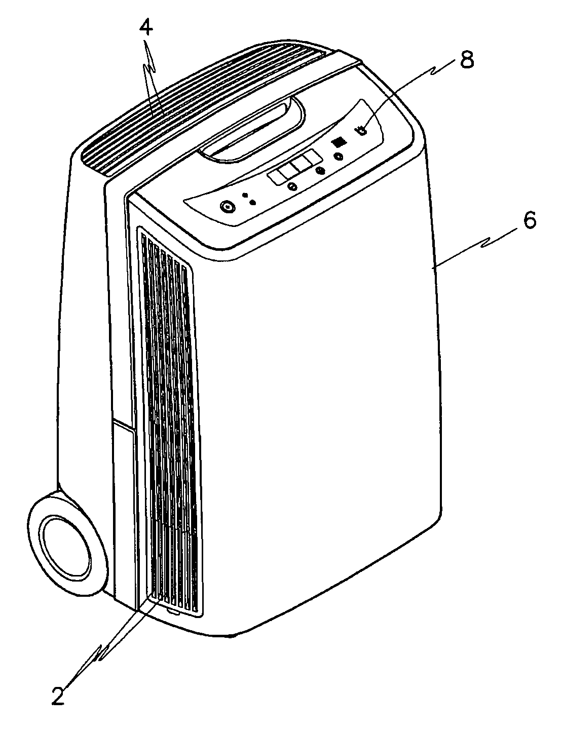
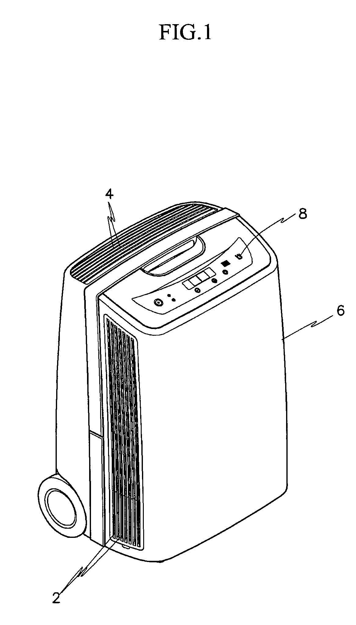
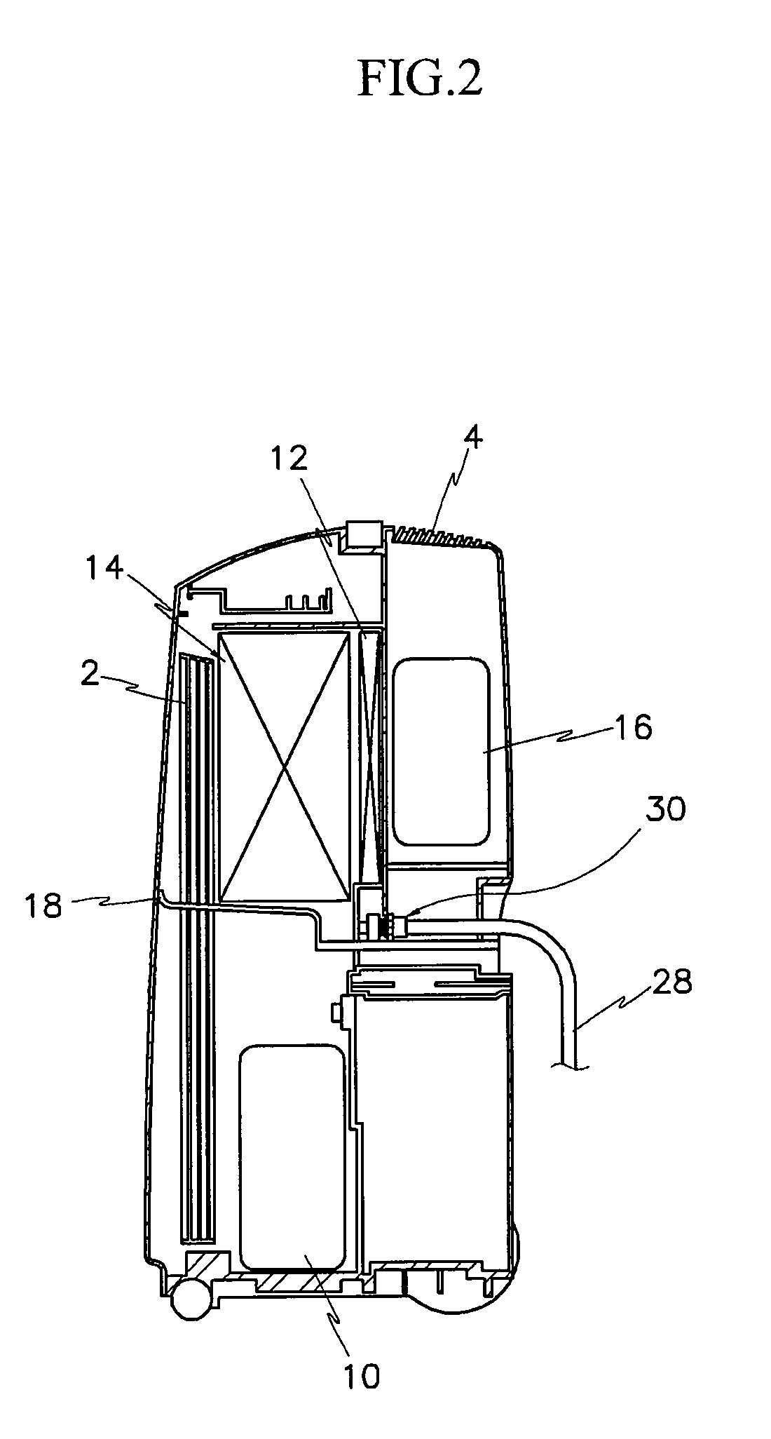
[0027]FIG. 1 is a perspective view of a dehumidifier according to an exemplary embodiment, and FIG. 2 is a cross-sectional side view of the dehumidifier of FIG. 1.

[0028]A humidifier includes a case 6 provided with an air inlet 2 and an air outlet 4, and a control panel 8 provided at an upper side of the case 6.

[0029]A dehumidifying unit is provided in the case 6. The dehumidifying unit includes a compressor 10 for compressing a gaseous refrigerant into a high temperature / pressure state, a condenser 12 for condensing the high temperature / pressure gaseous refrigerant from the compressor 10, and a vaporizer 14 for vaporizing the refrigerant that is reduced in pressure while passing through the condenser.

[0030]The dehumidifying unit includes a sucking unit 16 that sucks air into the case 6 so that the air can pass through the vaporizer 1...


PUM

PropertyMeasurementUnit
outer circumferenceaaaaaaaaaa
circumferenceaaaaaaaaaa
temperature/pressureaaaaaaaaaa

Abstract

A dehumidifier for continuously draining water generated by dehumidification to an external side is provided. The continuous drain-type dehumidifier includes a case having an air inlet and outlet, a dehumidifying unit that remove moisture from air introduced through the air inlet and discharges the air through the air outlet, a middle part member having a bottom portion on which water generated by the dehumidifying unit is dropped and provided with a water outlet, and a water leakage preventing unit that is provided on the water outlet to prevent the water from leaking. The water leakage preventing unit includes a drain nipple cap inserted into the water outlet, a drain nipple snap-fitted to the drain nipple cap, and a ring compressed between the drain nipple cap and the drain nipple and close-contacting an outer circumference of the water outlet.

Description

BACKGROUND OF THE INVENTION[0001](a) Field of the Invention[0002]The present invention relates to a continuous drain-type dehumidifier. More particularly, the present invention relates to a dehumidifier that can continuously drain water generated by dehumidification without storing the water in a water tank.[0003](b) Description of the Related Art[0004]A typical dehumidifier is an appliance for removing moisture from indoor air. There are various dehumidifiers using different dehumidifying methods.[0005]Among the dehumidifiers, a cooling-type dehumidifier using a cooling cycle in which moisture is removed from the air by condensing the moisture contained in the air when the air passes through a vaporizer.[0006]The dehumidifier includes a case defining an appearance of the dehumidifier and provided with an air inlet, an intake fan that is installed in the case to suck external air, a dehumidifying unit that removes moisture from the air sucked by the intake fan by condensing the mois...

Claims


Application Information

Patent Timeline
Patent Type & Authority Applications(United States)
IPC IPC(8): F25D21/14
CPCF24F3/1405F24F2013/227F24F13/222Y10S261/65
Inventor YOON, HEE-JONG
Owner WINIX
Why Eureka
Try Eureka