Driving motor controlling device of construction machine

Inactive Publication Date: 2006-10-05
NABLESCO CORP
View PDF4 Cites 6 Cited by
  • Summary
  • Abstract
  • Description
  • Claims
  • Application Information

AI Technical Summary

Benefits of technology

[0009] A first advantage of the present invention is to provide a driving motor controlling device of a construction machine, which is capable of suppressing heat balance of a driving motor from being lost when the construction machine begins to be driven after a warming up operation and suppressing an operation fault or failure of the driving motor due to a difference in thermal expansion in the driving motor.
[0010] A second advantage of the present invention is to provide a driving motor controlling device of a construction machine, which is capable of more surely suppressing cavitation from being created although a counterbalance valve is not used and preventing rising of a driving speed from being delayed upon start-up.
[0011] According to a first aspect of the invention for realizing the first advantage, there is provided a driving motor controlling device of a construction machine, included in the construction machine having a swivel joint interposed between an upper body and a lower body, the device comprising including a driving motor which is connected to a pump and a tank through the swivel joint, and a motor control valve which switches a state for connecting the pump and the tank to the driving motor such that the driving motor is controlled to a stop state, a normal rotation state, or a reverse rotation state, wherein the motor control valve has a neutral position for the stop state, a normal rotation position for the normal rotation state, and a reverse rotation position for the reverse rotation state, and is switched to the neutral position, the normal rotation position, or the reverse rotation position, based on a command from a control device manipulated by a operator and a pressure of an inflow side of hydraulic oil into the driving motor, wherein the motor control valve is disposed in the lower body in which the driving motor is disposed, and is integrally formed with the driving motor, and wherein, upon a warming up operation, the hydraulic oil discharged from the pump is circulated to the tank disposed in the upper body through the swivel joint and the motor control valve.
[0012] By this configuration, when a warming up operation of the construction machine is performed, the hydraulic oil discharged from the pump to the motor control valve disposed in the lower body in which the driving motor is disposed is circulated. Accordingly, the motor control valve becomes warm by the hydraulic oil which becomes warm by circulation, and thus the driving motor integrally formed with the motor control valve becomes warm. By this configuration, in the driving motor controlling device of the construction machine, when the construction machine begins to be driven after the warming up operation, the heat balance of the driving motor is prevented from being lost and thus the operation fault or failure of the driving motor due to the difference in the thermal expansion in the driving motor can be suppressed.
[0013] The motor control valve may be tandem-connected or serial-connected to control valves of hydraulic actuators different from the driving motor and may be provided at downstream of the control valves of the hydraulic actuators.
[0014] By this configuration, the hydraulic oil fed from the pump passes through the control valve of the hydraulic actuators and is fed to the motor control valve. Accordingly, pressure loss due to the length of the pipe which more becomes longer by a length corresponding to the motor control valve disposed in the lower body does not affect the hydraulic actuators. Therefore, it is possible to suppress energy efficiency from be reduced.

Problems solved by technology

At this state, when the construction machine begins to be driven, the warm hydraulic oil is rapidly fed to the cold driving motor and thus heat balance of the driving motor is lost.
In the driving motor controlling device disclosed in Japanese Unexamined Patent Application Publication No. 60-249707, when the construction machine begins to be driven after the warming up operation, an operation fault or failure of the driving motor may be caused due to a difference in thermal expansion.

Method used


Image

  • Driving motor controlling device of construction machine
  • Driving motor controlling device of construction machine
  • Driving motor controlling device of construction machine

Examples


first embodiment

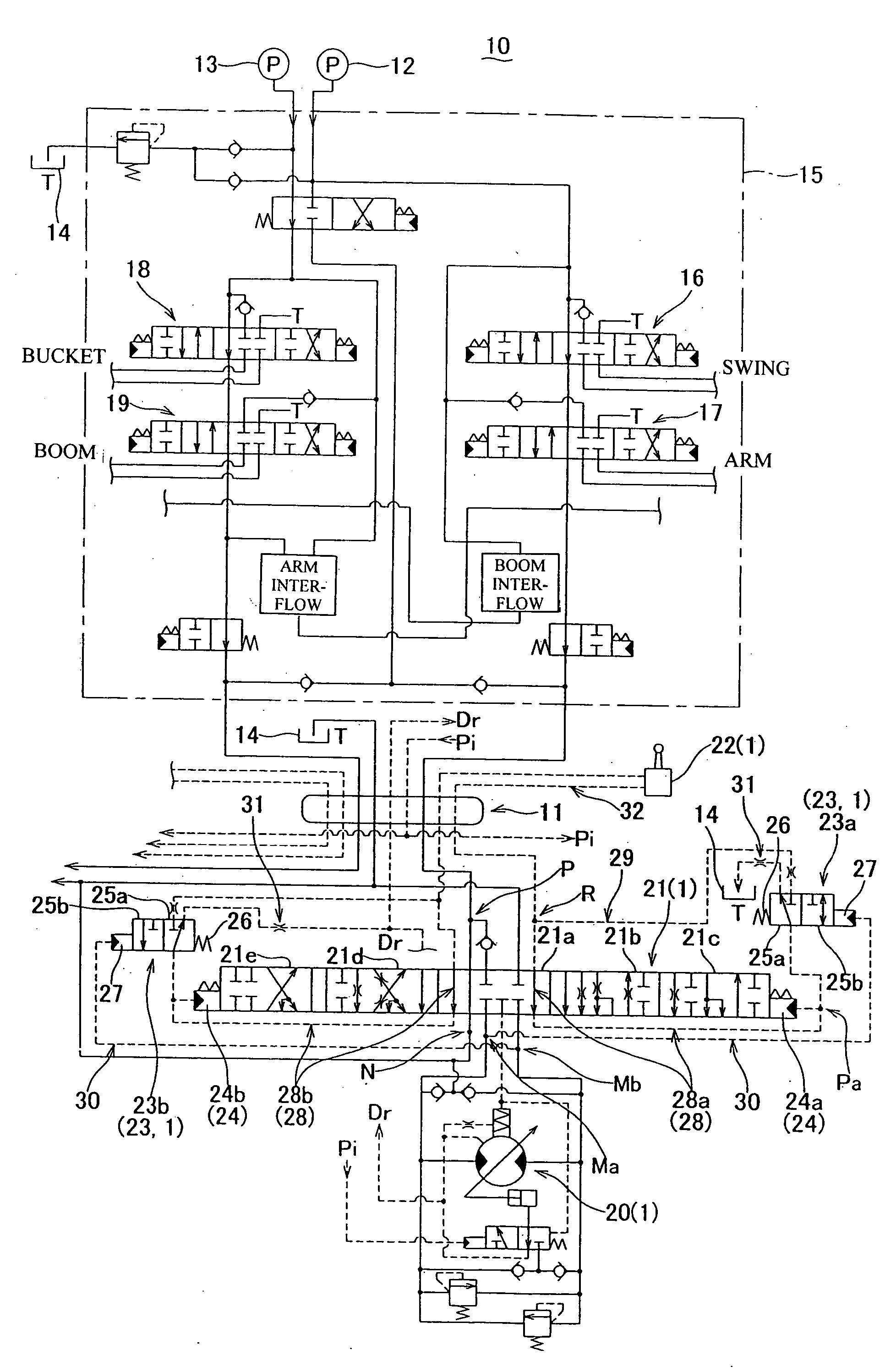
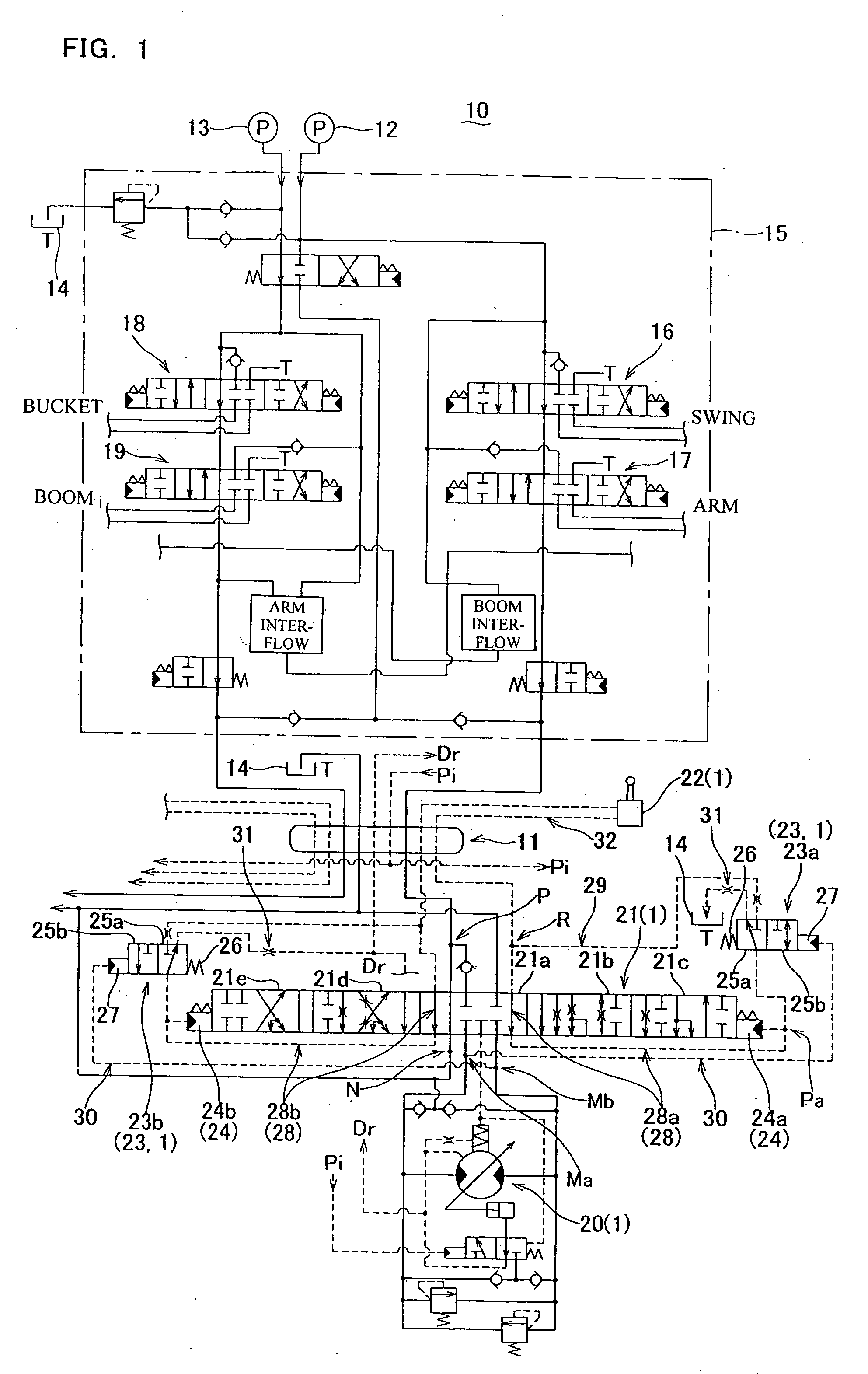
[0047]FIG. 1 is a view showing a hydraulic circuit included in a driving motor controlling device of a construction machine related to a first embodiment of the invention. As shown in FIG. 1, the construction machine in which a hydraulic circuit 10 is disposed has a lower body including a crawler body and an upper body disposed thereon, and a swivel joint 11 is disposed between the lower body and the upper body. In this construction machine, at least two hydraulic pumps such as a first pump 12 and a second pump 13 and a tank 14 are provided in the upper body. In addition, in the upper body, various kinds of hydraulic actuators to which hydraulic oil is fed from the pumps 12 and 13 are provided. In the lower body, a driving motor connected to the pumps 12 and 13 and the tank 14 through the swivel joint 11 is provided. In addition, in this construction machine, a right driving motor 20 and a left driving motor are provided, but only the right driving motor 20 is shown in FIG. 1. In th...

second embodiment

[0076] Next, a second embodiment of the invention will be described. FIGS. 3 and 4 are views showing a hydraulic circuit included in a driving motor controlling device of a construction machine related to a second embodiment of the invention. The construction machine having the hydraulic circuit 110 shown in FIGS. 3 and 4 includes a lower body including a crawler body and an upper body disposed thereon, and a swivel joint 111 is interposed between the upper body and the lower body (see FIG. 2).

[0077] In this construction machine, similar to the construction machine described in the first embodiment, at least two hydraulic pumps, such as a first pump 112 and a second pump 113, and a tank 114 are disposed in the upper body. In addition, in the upper body, various kinds of hydraulic actuators to which the hydraulic oil is fed from the pumps 112 and 113 are provided. In the lower body, a driving motor connected to the pumps 112 and 113 and the tank 114 through the swivel joint 111 is p...


PUM


Abstract

Provided is a driving motor controlling device of a construction machine, including a driving motor which is included in the construction machine having a swivel joint interposed between an upper body and a lower body, and is connected to a pump and a tank through the swivel joint, and a motor control valve which switches a state for connecting the pump and the tank to the driving motor such that the driving motor is controlled to a stop state, a normal rotation state, or a reverse rotation state, wherein the motor control valve has a neutral position for the stop state, a normal rotation position for the normal rotation state, and a reverse rotation position for the reverse rotation state, and is switched to the neutral position, the normal rotation position, or the reverse rotation position, based on a command from a control device manipulated by a operator and a pressure of an inflow side of hydraulic oil into the driving motor, wherein the motor control valve is disposed in the lower body in which the driving motor is disposed, and is integrally formed with the driving motor, and wherein, upon a warming up operation, the hydraulic oil discharged from the pump is circulated to the tank disposed in the upper body through the swivel joint and the motor control valve.

Description

BACKGROUND OF THE INVENTION [0001] 1. Technical Field [0002] The present invention relates to a driving motor controlling device of a construction machine, which has a driving motor connected to a pump and a tank through a swivel joint and a motor control valve for switching a state for connecting the pump and the tank to the driving motor such that the driving motor is controlled to any one of a stop state, a normal rotation state, and a reverse rotation state. [0003] 2. Related Art [0004] A driving motor controlling device of a construction machine (hereinafter, referred to as driving motor controlling device) which has a driving motor and a motor control valve for controlling an operation state of the driving motor is known as an example of related art (see Japanese Unexamined Patent Application Publication No. 60-249707). In the driving motor controlling device disclosed in Japanese Unexamined Patent Application Publication No. 60-249707, the motor control valve is integrally fo...

Claims


Application Information

Patent Timeline
IPC IPC(8): F16D31/02
CPCE02F9/123E02F9/2275E02F9/2267E02F9/2221E02F9/20E02F9/22
Inventor ANDO, TERUHISASHIMIZU, NOBUAKITSUNEMI, MASAHIROYAMAGUCHI, HITOSHI
Owner NABLESCO CORP
Why Eureka
Try Eureka