Soldering method, soldering device, bonding method, bonding device, and nozzle unit

a soldering device and soldering technology, applied in the direction of molten metal supplying equipment, packaging, machines/engines, etc., can solve the problem of insufficient ejection of the molten solder ball, the inability to maintain the inner pressure of the accommodating portion, and the difficulty of holding the solder ball. to achieve the effect of reliable ejection of the bonding member

Inactive Publication Date: 2006-10-05
TDK CORPARATION
View PDF7 Cites 41 Cited by
  • Summary
  • Abstract
  • Description
  • Claims
  • Application Information

AI Technical Summary

Problems solved by technology

However, as the electrodes and the peripheral members are reduced in size, it is becoming increasingly difficult to hold the solder ball 307 without unnecessarily bringing the forward end, etc. of the suction nozzle 301 into contact with the electrodes and the peripheral members.
When, for example, the solder ball 407 adheres to the inner wall surface of the accommodating portion 405, a gap is generated between the next solder ball 407 introduced into the accommodating portion 405 and the inner wall surface of the accommodating portion 405, and compressed gas leaks through this gap, with the result that the proper inner pressure cannot be maintained within the accommodating portion, and the ejection of the molten solder ball may not be effected to a sufficient degree.
Further, due to the adhering solder member, clogging may occur in the opening 403 of the nozzle 402.

Method used


Image

  • Soldering method, soldering device, bonding method, bonding device, and nozzle unit
  • Soldering method, soldering device, bonding method, bonding device, and nozzle unit
  • Soldering method, soldering device, bonding method, bonding device, and nozzle unit

Examples


embodiment 1

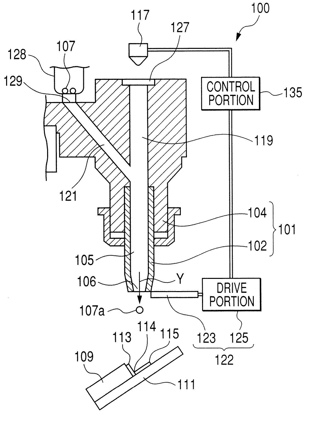
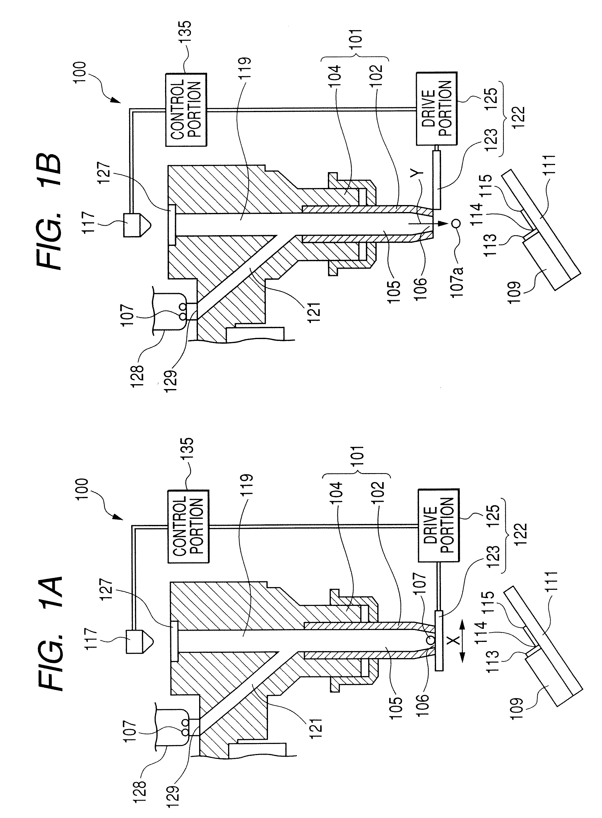
[0034]FIGS. 1A and 1B are partial sectional views of a soldering device according to an embodiment of the present invention. In FIG. 1A, the stopper of the device is in a closing position, and in FIG. 1B, the stopper is in an opening position. In the device of the embodiment shown in FIGS. 1A and 1B, electrical connection is effected between a substantially rectangular magnetic head slider 109 and a flexure 111 having a form of a thin plate to which the slider 109 is to be attached by using a solder member, that is, a spherical solder ball 107.

[0035] First, the construction of the slider 109 and the flexure 111 to be soldered will be described. A slider electrode 113 formed of a metal plate is provided on one end surface of the slider 109. On the flexure 111, there is provided a flexure electrode 115 formed of a metal plate, with the slider electrode 113 and the flexure electrode 115 forming a corner portion 114 at an angle of approximately 90 degrees. A molten solder ball 107a is ...

embodiment 2

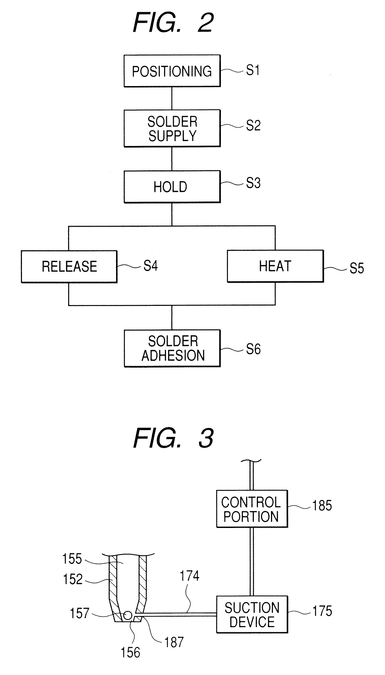
[0053] While in Embodiment 1 described above the opening / closing portion 122 is used, it is also possible to effect holding and releasing of the solder ball by using suction means. In the following, Embodiment 2, which uses suction means, will be described.

[0054]FIG. 3 is a sectional view of a part of a soldering device equipped with a suction device. Except for the components shown in FIG. 3, components of the soldering device of this embodiment are the same as those of the soldering device of FIG. 1, so the components common to these embodiments are not shown in FIG. 3. A nozzle 152 has a suction port 187 in the vicinity of an opening 156. The suction port 187 extends horizontally (as shown in FIG. 3) through the wall of the nozzle 152, and communicates with an accommodating portion 155. Further, one end of a suction tube 174 is connected to the suction port 187. Suction means, that is, a suction device 175, which generates a suction force, is connected to the other end of the su...

embodiment 3

[0060] In the following, a soldering device according to Embodiment 3 of the present invention will be described, in which compressed gas is imparted to the solder member to eject the solder member. FIG. 4 is a partial sectional view of a soldering device according to Embodiment 3 of the present invention.

[0061] A slider 1151 and a flexure 1155, which are to be soldered to each other, are arranged such that slider electrodes 1153 and flexure electrodes 1157 are at an angle of elevation of substantially 90 degrees. There are provided at least four slider electrodes and four flexure electrodes. Temporary positioning is effected on the slider 1151 and the flexure 1155 by an adhesive or a grasping mechanism, and a groove 1159 at an angle of elevation of approximately 90 degrees is formed by the electrodes of the slider 1151 and the flexure 1155. Positioning is effected on a solder nozzle 1102 such that it substantially corresponds to the central position in the width direction (the dir...


PUM

PropertyMeasurementUnit
angleaaaaaaaaaa
inclination angleaaaaaaaaaa

Abstract

Provided is a nozzle unit for use in a bonding device in which bonding between a first member and a second member is effected by providing a bonding member that has been melted by heating at a bonding position where the first member and the second member are to be bonded to each other. The nozzle unit includes: a cylindrical nozzle assembly having an accommodating space accommodating the bonding member, and an opening which allows ejection of the bonding member accommodated in the accommodating space onto the bonding position, which has a diameter larger than the diameter of the bonding member, and which communicates with the accommodating space; and a holding / releasing member for releasably holding the bonding member within the accommodating space.

Description

BACKGROUND OF THE INVENTION [0001] 1. Field of the Invention [0002] The present invention relates to a bonding method and a bonding device in which a bonding member is used to bond a first member to a second member. [0003] 2. Related Background Art [0004] In a magnetic head manufacturing process, the bonding between a magnetic head slider electrode and a flexure electrode is effected by soldering using a solder ball. To be more specific, the two electrodes are arranged at an angular interval of 90 degrees, and a solder ball is arranged between the electrodes. The ball is melted by heat radiation or the like to effect electrical bonding between these electrodes. In the following, a conventional solder ball soldering device will be described with reference to the drawings. [0005]FIG. 9 is a partial sectional view of a suction nozzle for a soldering process using a conventional soldering device 300. In FIG. 9, reference numeral 309 indicates a slider formed substantially as a parallele...

Claims


Application Information

Patent Timeline
Patent Type & Authority Applications(United States)
IPC IPC(8): B23K31/00B23K1/00B23K3/06
CPCB23K1/0056B23K3/0623H05K3/3442H05K3/3478H05K3/3494H01L2224/742H05K2203/0195H05K2203/041H05K2203/082H05K2203/107H05K2201/10727
Inventor WAGOH, TATSUYAMIZUNO, TORUSHINDO, OSAMU
Owner TDK CORPARATION
Why Eureka
Try Eureka