

System for detecting a container or contents of the container
- Summary
- Abstract
- Description
- Claims
- Application Information
AI Technical Summary
Problems solved by technology
Method used
Image

Examples
first embodiment
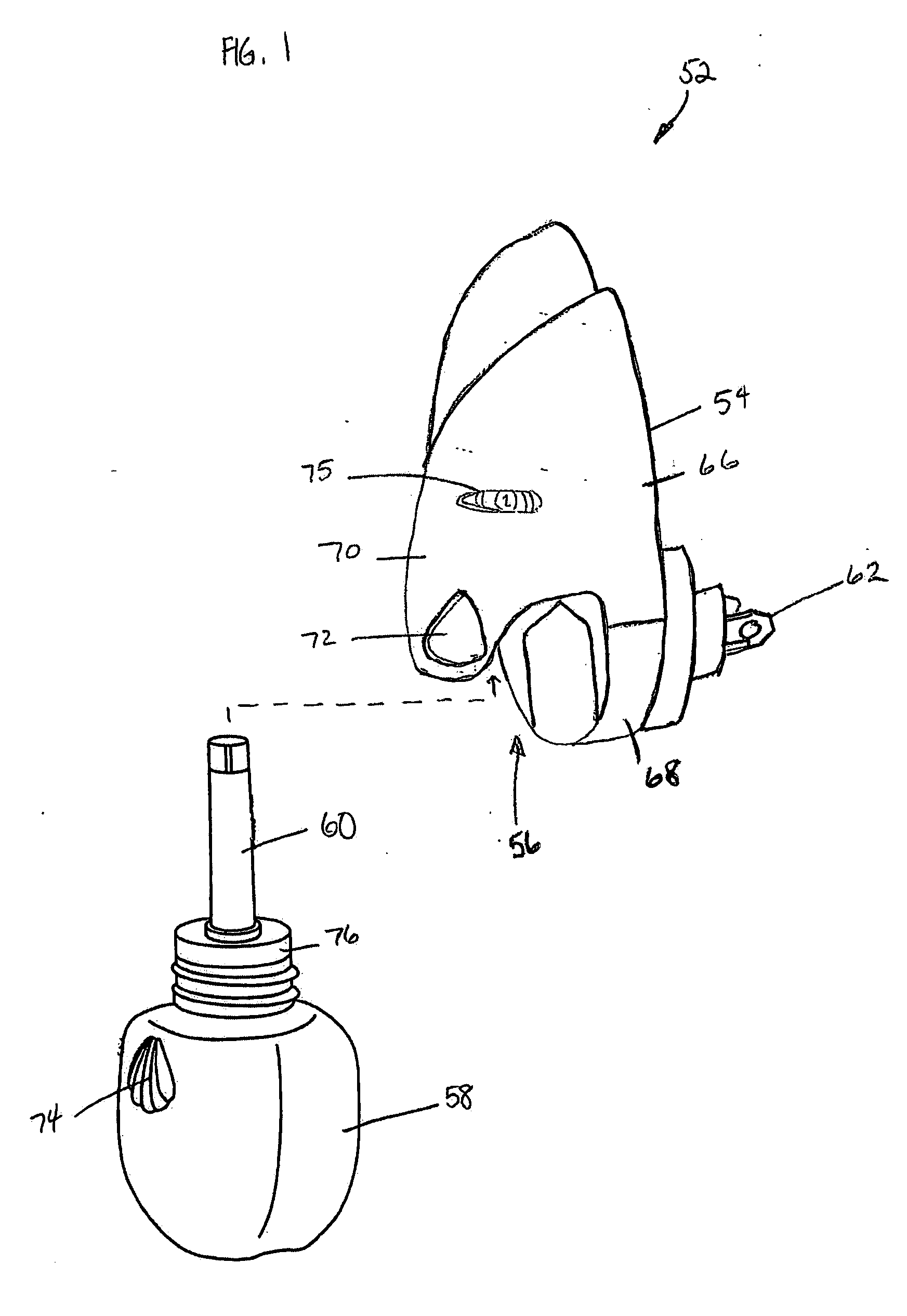
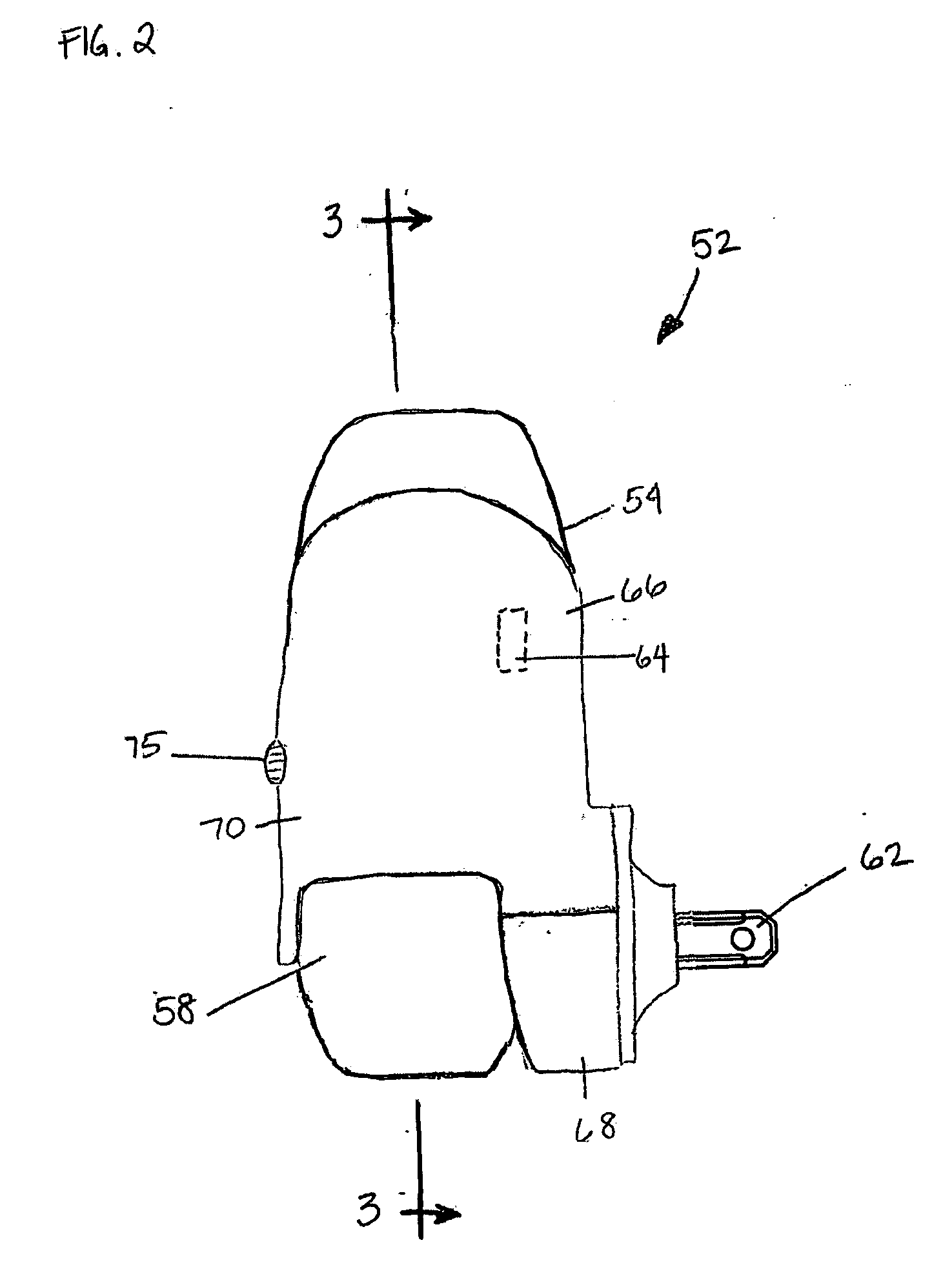
[0049] As seen in FIGS. 3-7, the detection system of the present invention as incorporated into the diffuser 52 of FIGS. 1 and 2 includes a light emitter 80 and a light receiver 82 disposed on opposite sides of the wick 60 that extends from the container 58. Illustratively, the light emitter 80 is an LED, but may also be any other lighting element that produces infrared, ultraviolet, red light, and / or visible light. Optionally, the light emitter 80 may be a modulated light source and / or may be a colored LED. An example of a suitable LED is a red LED modulated at 10 kHz with a model number L7113SECH from Kingbright Corporation of Taipei, Taiwan. Selection of the light emitter may depend on many factors, including, but not limited to, the necessary luminous intensity, the necessary viewing angle, the light emitter size, the desired color, the desired wavelength, the distance or placement of the light emitter within the diffuser, the electronics circuitry and / or functionality used in t...
second embodiment
[0059] As seen in FIGS. 8-11, the detection system of the present invention as incorporated into the diffuser 52 of FIGS. 1 and 2 includes a light emitter 180 and a light receiver 182 disposed around a wick 160 that extends from a container 158. In this embodiment, the light emitter 180 and light receiver 182 are at an approximate right angle to one another, but may also be at any other desirable or suitable angle wherein the light receiver 182 can potentially detect light from the light emitter 180. Also in this embodiment, the light emitter 180 is an LED and the light receiver 182 is a phototransistor, but either may also be any other device that emits or receives light as described herein or known in the art. The LED of FIGS. 8-11 may be slightly offset from a center of the wick 160 so as to avoid partial illumination of the wick 160 in front of the light receiver 182. The light receiver 82 is disposed close to the wick to reduce or minimize receipt of stray light by the receiver...
third embodiment
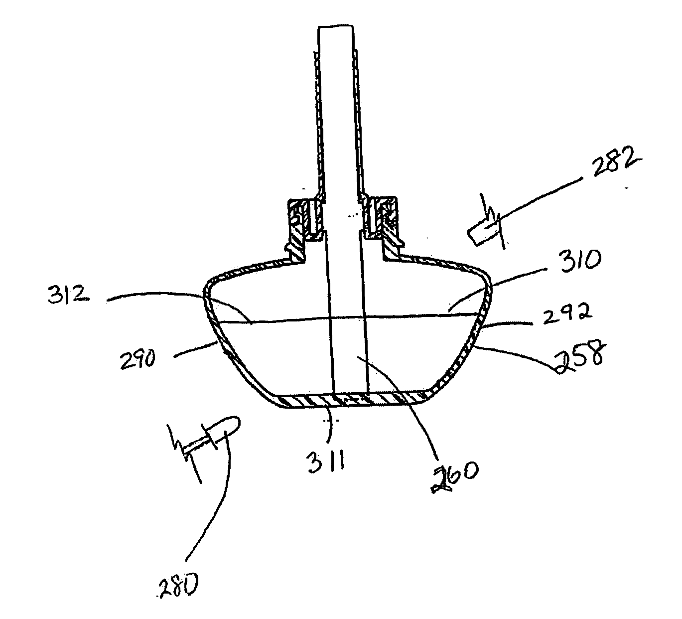
[0066]FIGS. 15 and 16 depict the detection system of the present invention as incorporated into the diffuser 252 of FIGS. 12-14, although the detection system may be incorporated into any diffuser. The detection system includes a light emitter 280 and a light receiver 282 disposed substantially in line with one another around the container 258 and in light communication with one another through the liquid active material in the container 258. The light emitter 280 is an LED and the light receiver 282 is a phototransistor, but as with other embodiments, any light emitter(s) and / or light receiver(s) known in the art may be employed. If one of the light emitter 280 and the light receiver 282 is positioned above a fill-level 310 of a full container 258 and the other of the emitter 280 or receiver 282 is located at a bottom 311 of the container 258, as seen in FIGS. 15 and 16, an empty state (FIG. 16) of the container 258 may be detected. In this case, the light receiver 282 receives lig...
PUM
 Abstract
Description
Claims
Application Information