Method and system for elastic signal pipelining

a technology of elastic signal and pipelining, applied in the field of signal propagation, can solve the problems of ensuring the reliable transmission of signals between the various components of such devices, and the design and fabrication of high-performance signaling mechanisms for digital integrated circuit devices has become a significant challeng

Active Publication Date: 2006-10-05
INTELLECTUAL VENTURES HOLDING 81 LLC
View PDF25 Cites 41 Cited by
  • Summary
  • Abstract
  • Description
  • Claims
  • Application Information

AI Technical Summary

Problems solved by technology

The design and fabrication of high-performance signaling mechanisms for digital integrated circuit devices has become a significant challenge.
For example, with respect to high-performan

Method used


Image

  • Method and system for elastic signal pipelining
  • Method and system for elastic signal pipelining
  • Method and system for elastic signal pipelining

Examples


Embodiment Construction

[0011] Reference will now be made in detail to the preferred embodiments of the present invention, examples of which are illustrated in the accompanying drawings. While the invention will be described in conjunction with the preferred embodiments, it will be understood that they are not intended to limit the invention to these embodiments. On the contrary, the invention is intended to cover alternatives, modifications and equivalents, which may be included within the spirit and scope of the invention as defined by the appended claims. Furthermore, in the following detailed description of embodiments of the present invention, numerous specific details are set forth in order to provide a thorough understanding of the present invention. However, it will be recognized by one of ordinary skill in the art that the present invention may be practiced without these specific details. In other instances, well-known methods, procedures, components, and circuits have not been described in detail...


PUM


Abstract

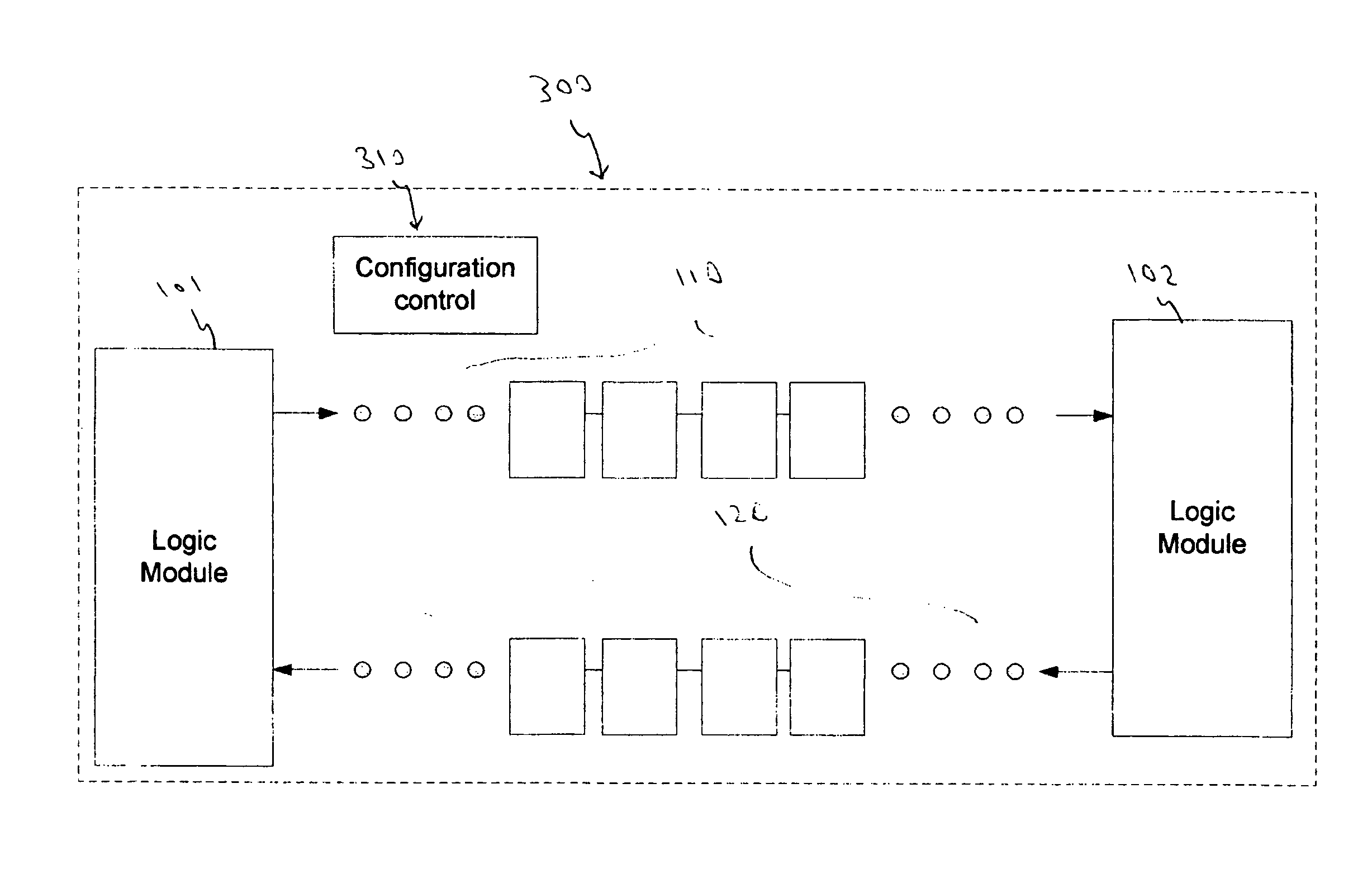
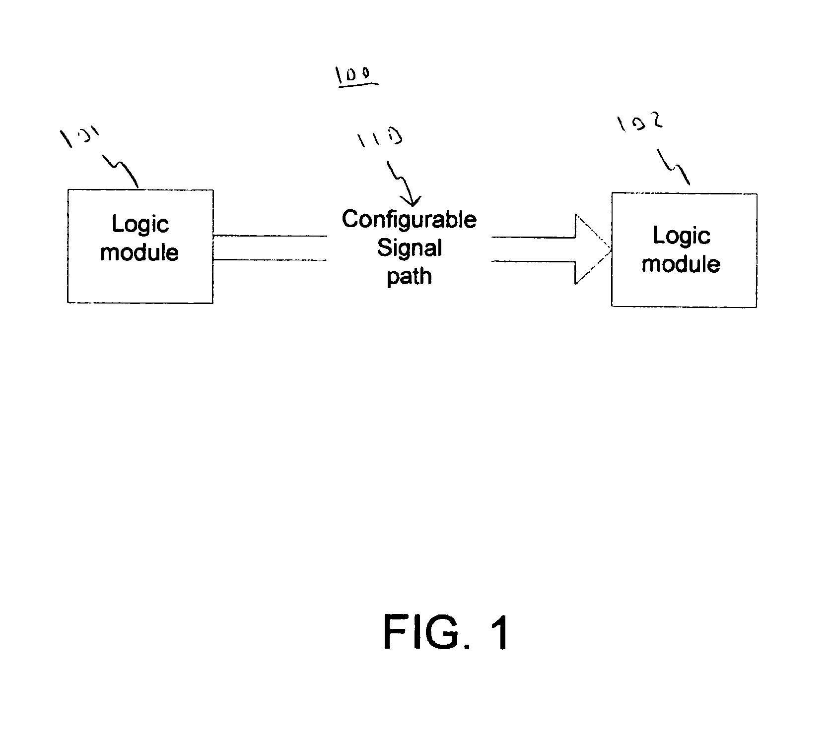
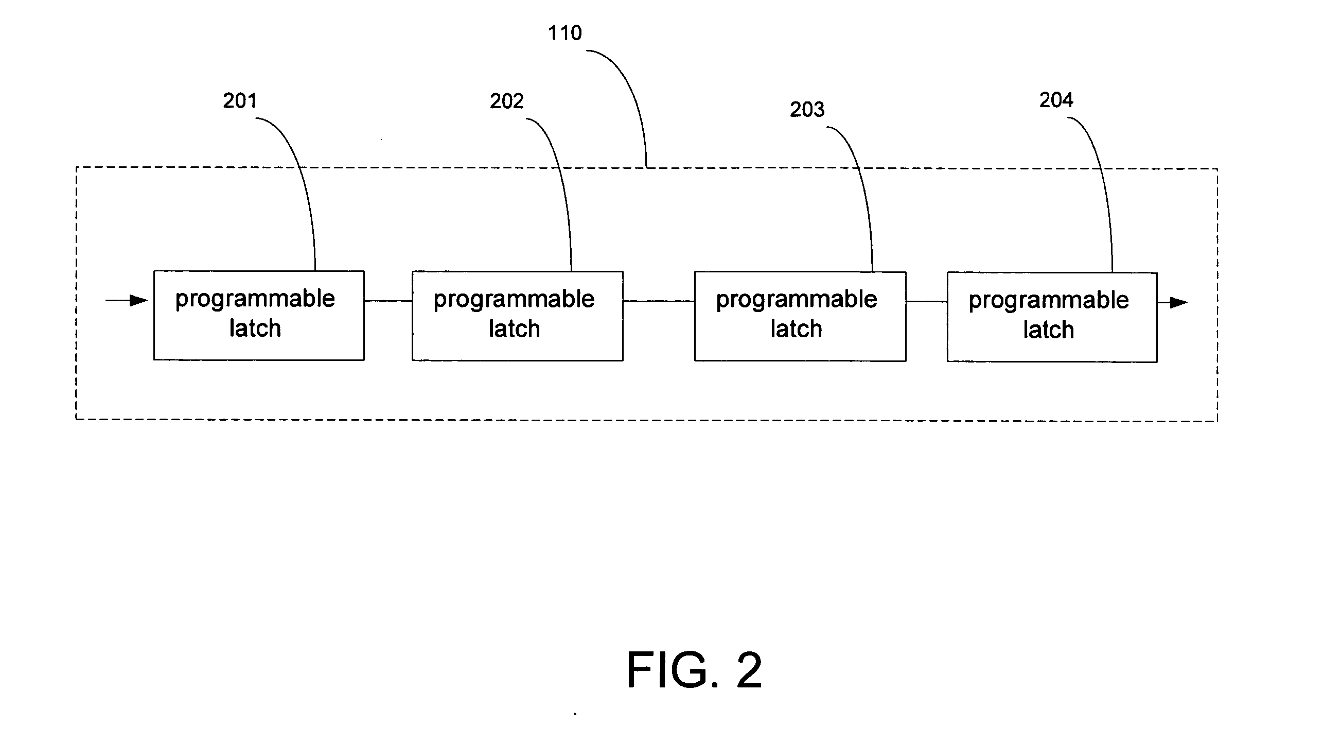
A method for configuring a signal path within a digital integrated circuit. The method includes transmitting an output from a first logic module, receiving the output at a second logic module, and conveying the output from the first logic module to the second logic module by using a configurable signal path. The configurable signal path is variable by selectively including at least one latch.

Description

TECHNICAL FIELD [0001] The present invention relates to signal propagation for digital integrated circuit devices. BACKGROUND ART [0002] The design and fabrication of high-performance signaling mechanisms for digital integrated circuit devices has become a significant challenge. For example, with respect to high-performance digital integrated circuit devices operating at high frequencies, ensuring the reliable transmission of signals between the various components of such devices has become problematic. In the past, slower clock speeds allowed sufficient margins in the timing constraints for signal propagation delay. However, modern integrated circuit designs require exacting control of critical timing specifications, and design parameters must be strictly maintained to keep the entire system in balance. Additionally, the system should run efficiently across different clock frequencies. Optimizations to ensure stable high-frequency operation should not unduly penalize the system dur...

Claims


Application Information

Patent Timeline
IPC IPC(8): H03K19/173
CPCG06F9/3869
Inventor ROZAS, GUILLERMO J.MASLEID, ROBERT P.
Owner INTELLECTUAL VENTURES HOLDING 81 LLC
Why Eureka
Try Eureka