Device with hinged USB port
- Summary
- Abstract
- Description
- Claims
- Application Information
AI Technical Summary
Benefits of technology
Problems solved by technology
Method used
Image
Examples
first embodiment
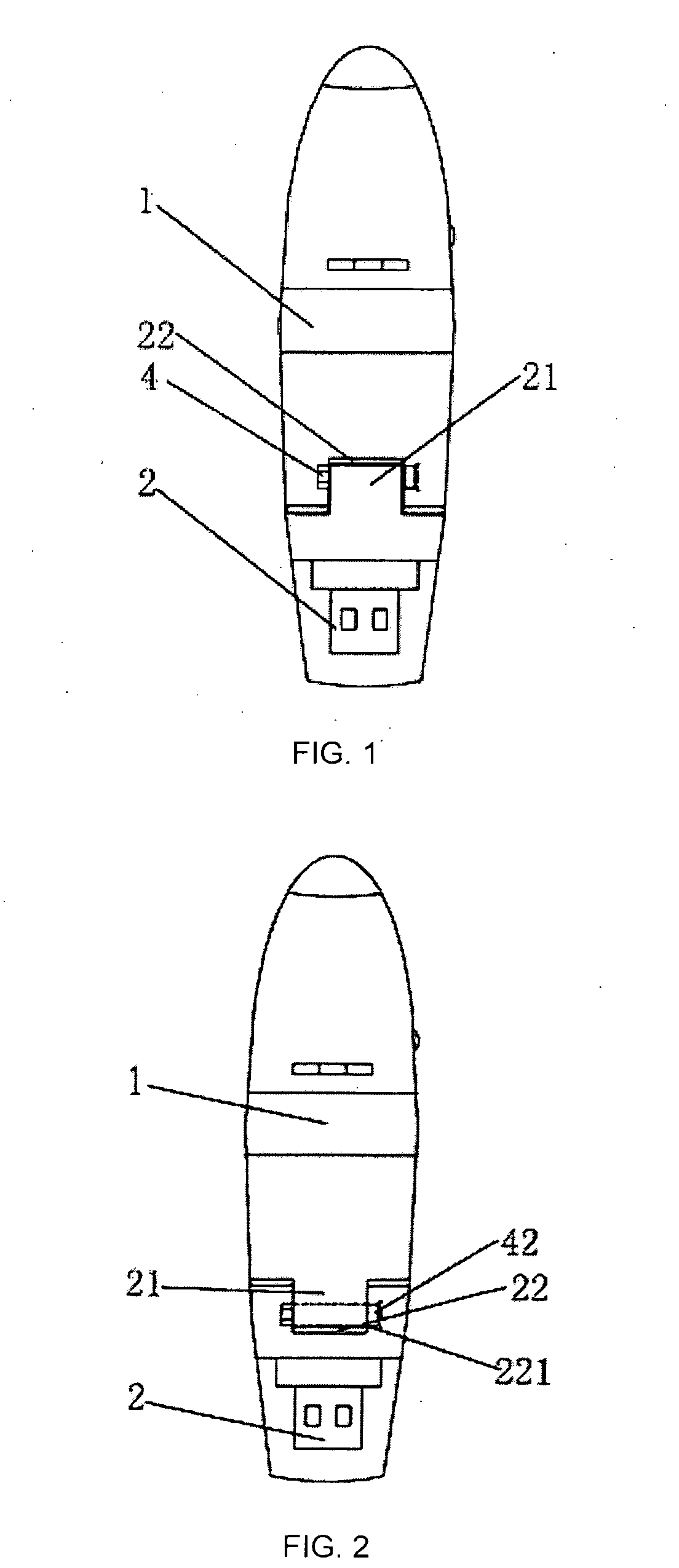
[0023]FIG. 1 shows the present invention, which is an application in the form of a USB drive device or MP3. At the foldable end of the USB drive device or MP3 1, there is a recess in the centre which forms a receiving slot 22. On each of the two sides of the receiving slot 22, there is an insertion hole respectively for insertion of a hinge shaft 4. A USB connector 2 has an integrally formed protruding part 21, the shape and position of which correspond to the receiving slot 22. The protruding part 21 is inserted into the receiving slot 22 and has a through hole in position corresponding to the insertion holes of the receiving slot 22 for insertion of the hinge shaft 4. The hinge shaft 4 connects the USB connector 2 and the USB drive device or MP3 1 in a hinged manner. Data cables pass through the through holes of the hinge shaft 4 and connect to the USB connector 2 and the USB drive device or MP3 1 respectively.
second embodiment
[0024]FIG. 2 shows the present invention, which is an application in the form of a blue-tooth device or mini digital camera. At the foldable end of a USB connector 2 which connects to the blue-tooth device or mini digital camera 1, there is a recess in the centre which forms a receiving slot 22. On each of the two sides of the receiving slot 22, there is an insertion hole 221 respectively for insertion of a positioning pin 42. The blue-tooth device or mini digital camera 1 has an integrally formed protruding part 21, the shape and position of which correspond to the receiving slot 22. The protruding part 21 has the positioning pin 42 protruding therefrom in position corresponding to the insertion holes 221 of the receiving slot 22. The protruding part 21 is inserted into the receiving slot 22 with the positioning pin 42 inserted into the insertion holes 221. The positioning pin 42 connects the USB connector 2 and the blue-tooth device or mini digital camera 1 in a hinged manner. Con...
third embodiment
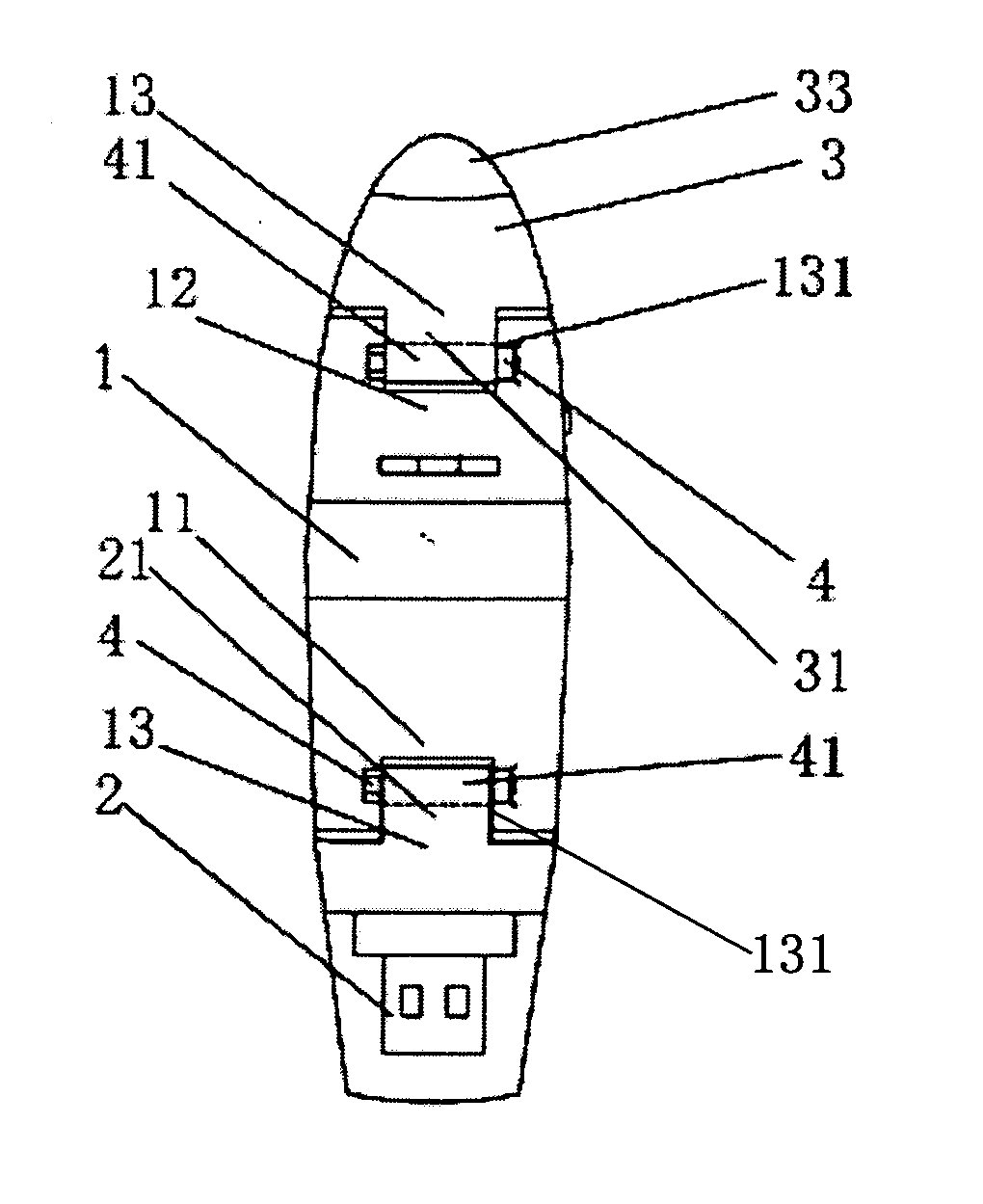
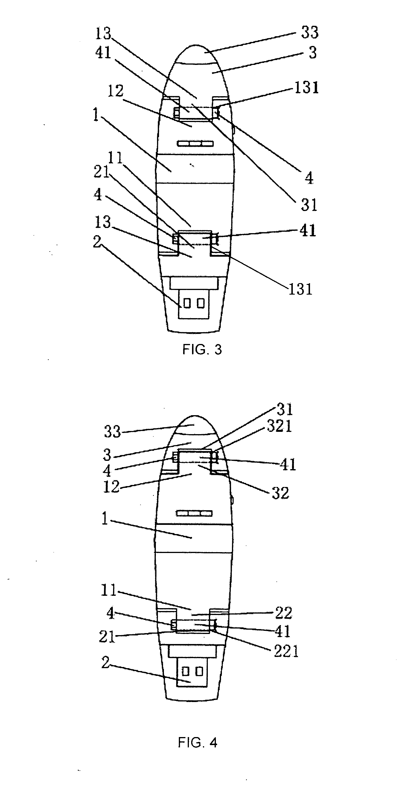
[0025]FIG. 3, FIG. 6 and FIG. 7 show the present invention, which is an application in the form of a USB chargeable lamp. One end 11 of the battery charger 1 of the USB chargeable lamp connects to a USB connector 2 in a hinged manner. The other end 12 of the battery charger 1 connects to a lighting device 3 in a hinged manner. At each end of the battery charger 1, there is a recess in the centre which forms a receiving slot 13. On each of the two sides of the receiving slot 13, there is an insertion hole 131 respectively for insertion of a hinge shaft 4. Each of the USB connector 2 and the lighting device 3 has an integrally formed protruding part 21, 31, the shape and position of which correspond to the respective receiving slot 13. Each protruding part 21, 31 is inserted into the respective receiving slot 13 and has a through hole 41 in position corresponding to the respective insertion hole 131 of the receiving slot 13 for insertion of the respective hinge shaft 4. The hinge shaf...
PUM
 Abstract
Description
Claims
Application Information
 - R&D
- Intellectual Property
- Life Sciences
- Materials
- Tech Scout
- Unparalleled Data Quality
- Higher Quality Content
- 60% Fewer Hallucinations
Browse by: Latest US Patents, China's latest patents, Technical Efficacy Thesaurus, Application Domain, Technology Topic, Popular Technical Reports.
© 2025 PatSnap. All rights reserved.Legal|Privacy policy|Modern Slavery Act Transparency Statement|Sitemap|About US| Contact US: help@patsnap.com


