Electronic apparatus, fan unit, and subrack

a technology for electrical equipment and subracks, applied in electrical equipment casings/cabinets/drawers, cooling/ventilation/heating modifications, instruments, etc., can solve the problems of dimensional limitations of the fan unit, lack of cooling capacity of a single radial fan, and fear of not having the requisite cooling capacity secured, etc., to achieve the effect of enhancing the accommodation efficiency of the subrack

Inactive Publication Date: 2006-10-05
NEC CORP
View PDF7 Cites 10 Cited by
  • Summary
  • Abstract
  • Description
  • Claims
  • Application Information

AI Technical Summary

Benefits of technology

[0017] According to the present invention, it is possible to obtain an electronic apparatus with a cooling structure capable of securing the requisite cooling capacity for cooling the electronic apparatus and electronic component modules and capable of enhancing the accommodation efficiency of a subrack, and a fan unit and a subrack that can be suitably used in the electronic apparatus.

Problems solved by technology

The direction of the cooling air has a great influence on the arrangement of the subracks and, at the same time, imparts dimensional limitations to the fan units.
However, in the case of a thin-type radial fan, there is involved a shortage of cooling capacity with a single radial fan.
However, JP 2000-59061 A and the example shown in FIGS. 2A and 2B only teach the installment of a single row of radial fans; with a single row of radial fans, there is a fear of the requisite cooling capacity not being secured.
As a result, a deterioration in cooling capacity is involved.
However, it has been rather difficult to obtain a radio base station apparatus capable of enhancing the accommodation efficiency of the subrack and securing the requisite cooling capacity.

Method used


Image

  • Electronic apparatus, fan unit, and subrack
  • Electronic apparatus, fan unit, and subrack
  • Electronic apparatus, fan unit, and subrack

Examples


Embodiment Construction

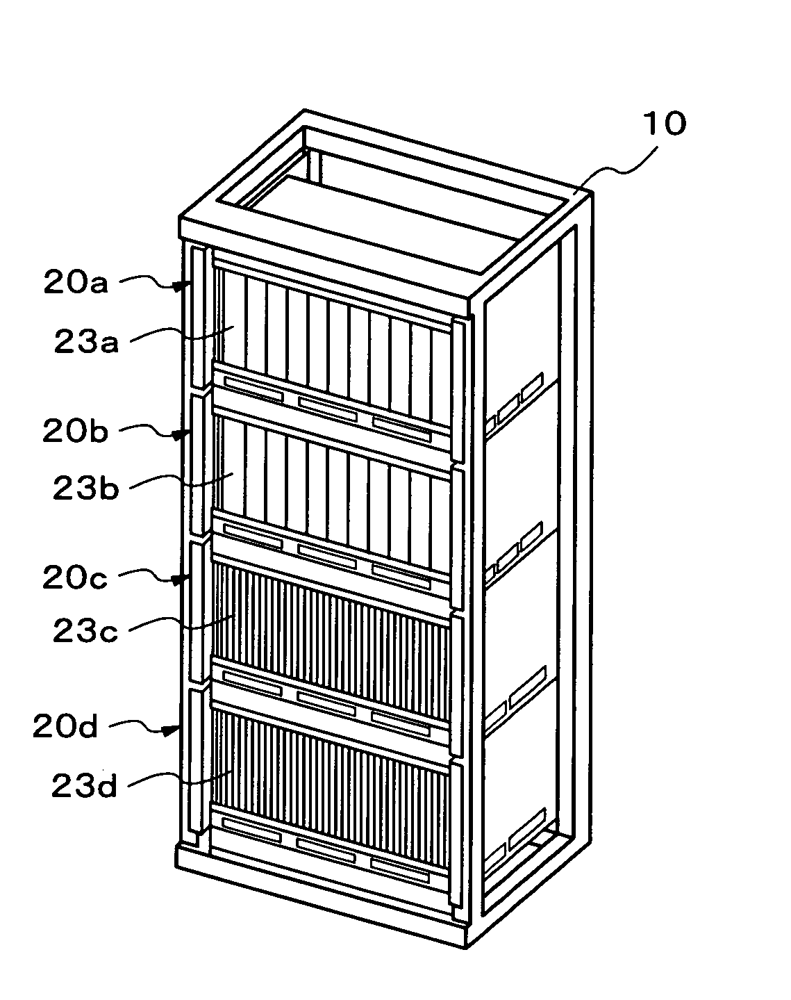
[0049] Next, exemplary embodiments of the present invention will be described with reference to the drawings. FIGS. 3A and 3B are a front perspective view and a rear perspective view, respectively, of an electronic apparatus, i.e., a radio base station apparatus to be installed indoors, according to a first exemplary embodiment of the present invention. As shown in the figures, the radio base station apparatus has an open-rack structure, and includes an apparatus frame 10, and subracks 20a through 20d stacked, inside the apparatus frame 10, in four stages in a height direction.

[0050] The subracks 20a through 20d respectively accommodate electronic component module groups (inner modules) 23a through 23d inserted therein to be arranged so as to be perpendicular to a direction of a bottom surface of the apparatus frame 10. Each module of the electronic component module groups 23a through 23d includes an electronic circuit board and a front panel. In FIGS. 3A and 3B, the subrack 20a an...


PUM


Abstract

The fan unit according to the present invention includes a plurality of radial fans; and a unit casing which accommodates the radial fans and includes a first member and a second member, each of which has exhaust ports allowing transmission of at least a part of output air from the radial fans.

Description

BACKGROUND OF THE INVENTION [0001] 1. Field of the Invention [0002] The present invention relates to an electronic apparatus, a fan unit, and a subrack, and more specifically, to an electronic apparatus with a cooling structure particularly suitable for a radio base station apparatus, a fan unit, and a subrack suitable for cooling the electronic apparatus. [0003] 2. Description of the Related Art [0004] A cooling structure for cooling an electronic apparatus by using an axial fan is disclosed, for example, in Japanese Patent Laid-Open Publication JP 2000-59061 A and JP 2002-118387 A. JP 2000-59061 A discloses an electronic apparatus equipped with a casing, and a plurality of electronic component modules accommodated in the casing. Here, a fan in the electronic apparatus sucks the air within the casing to generate an airflow inside the casing, and the sucked air is discharged through an exhaust port. JP 2002-118387 A discloses a computer cooling structure. Here, in a computer equippe...

Claims


Application Information

Patent Timeline
Patent Type & Authority Applications(United States)
IPC IPC(8): H05K5/00
CPCH05K7/20563
Inventor MATSUZAWA, TADASHIKUSAKI, SYUICHI
Owner NEC CORP
Why Eureka
Try Eureka