Puncture device

Inactive Publication Date: 2006-10-05
ARKRAY INC
View PDF13 Cites 146 Cited by
  • Summary
  • Abstract
  • Description
  • Claims
  • Application Information

AI Technical Summary

Benefits of technology

[0007] An object of the present invention is to reduce the load of the user

Problems solved by technology

This operation is troublesome and

Method used


Image

  • Puncture device
  • Puncture device
  • Puncture device

Examples


Embodiment Construction

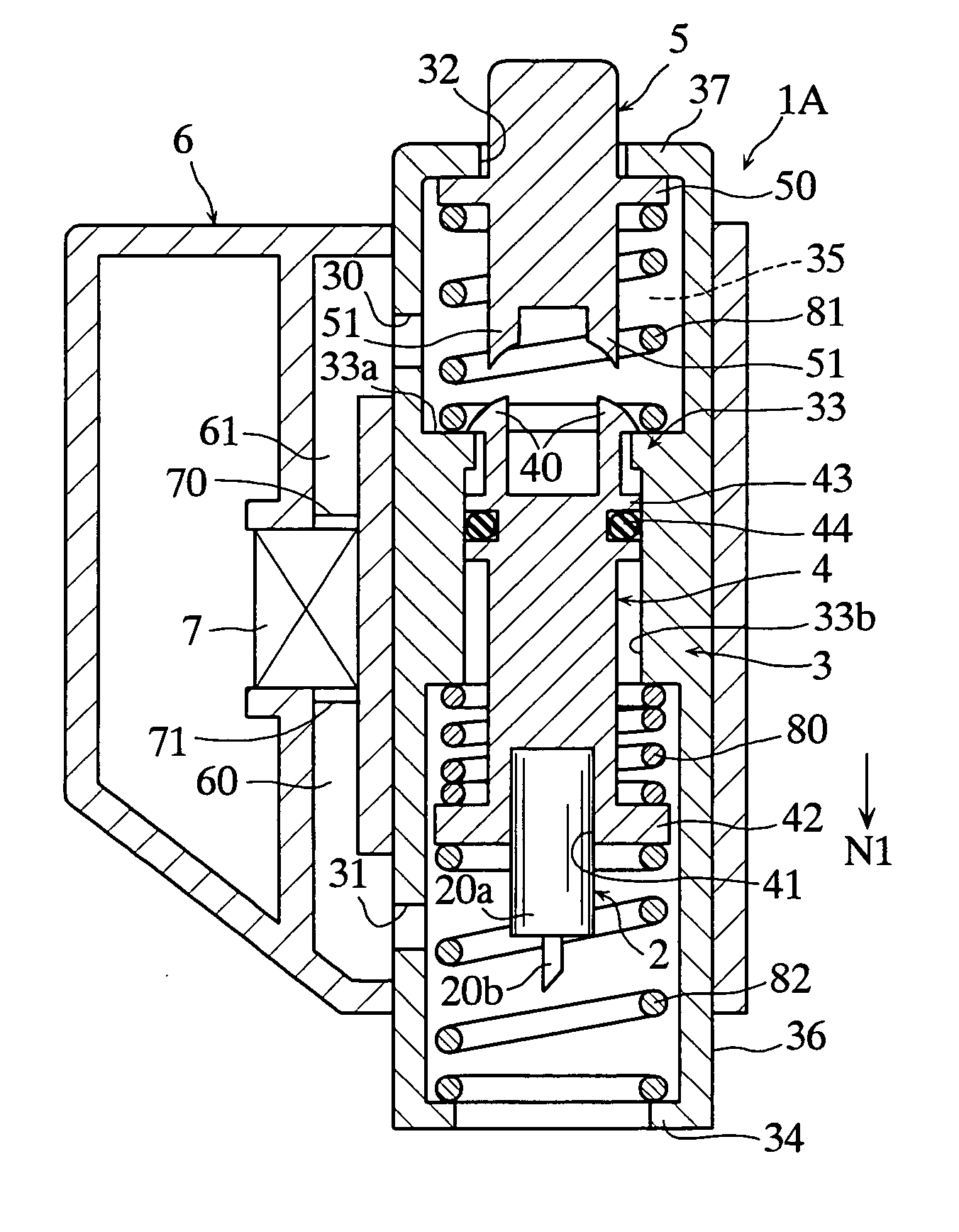
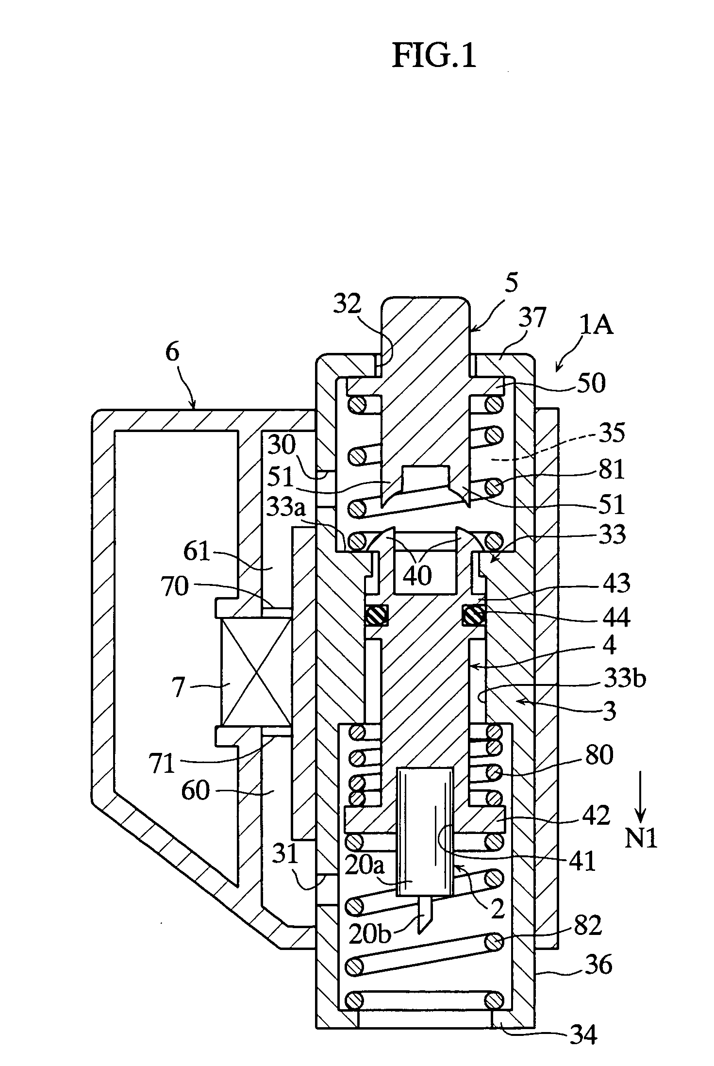
[0033] As shown in FIG. 1, a lancet 2 is attached to a lancing device 1A in use. The lancet 2 includes a body 20a and a needle 20b protruding from the body. The needle 20b is made of e.g. metal, and the body 20a is made of e.g. synthetic resin. The needle 20b may be integrally embedded in the body 20a when the body is produced by insert molding, for example.

[0034] The lancing device 1A includes a housing 3, a lancet holder 4, an operating cap 5, a case 6, and an electrical pump 7.

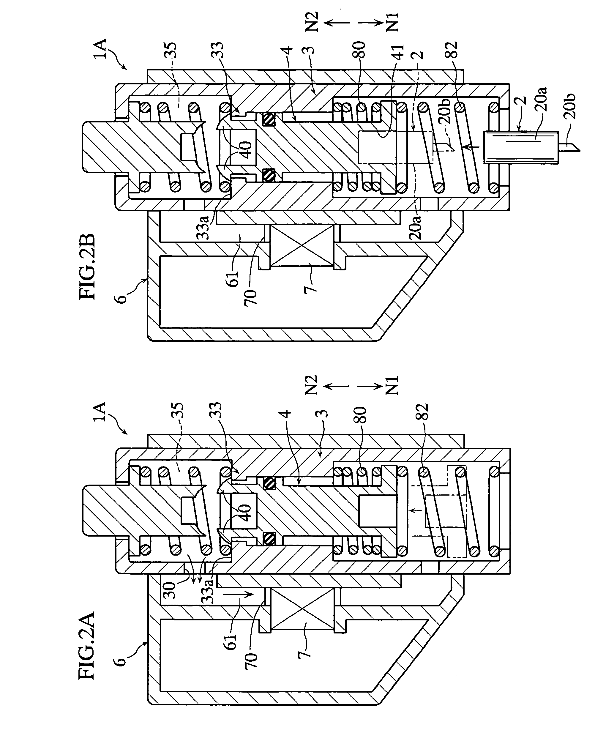
[0035] The housing 3 accommodates the lancet holder 4. The housing 3 includes through-holes 30, 31, 32, projections 33, 34, a decompression space 35, and a contact portion 36. As shown in FIG. 2A, the through-hole 30 is used for discharging the air out of the decompression space 35. As shown in FIG. 3, the through-hole 31 is used for discharging the air out of the contact portion 36. As seen from in FIGS. 1-4A, 4B, the through-hole 32 allows the movement of the operating cap 5, and is used for introducing...


PUM


Abstract

The present invention relates to a lancing device (1A) that includes a moving member (4) for moving a needle (20b) in an advancing direction (N1) from a standby position to a puncturing position, and also includes a contact portion (36) for contacting with a puncturing target (S). The lancing device (1A) applies a suctioning force to the moving member (4) to move the moving member (4) in a retreating direction so that the moving member (4) is brought to the standby position. The lancing device (1A) is provided with a decompression space (35) which is decompressed for applying the suctioning force to the moving member (4). Preferably, the pressure in the decompression space (35) is reduced to be smaller than the atmospheric pressure by a predetermined value, thereby moving the moving member (4) in the retreating direction.

Description

TECHNICAL FIELD [0001] The present invention relates to a device for sticking a needle into the skin to obtain a sample of body fluid such as blood or a tissue. BACKGROUND ART [0002] For obtaining a sample of blood from skin, use may be made of a lancing device which includes a needle held by a moving member and a housing accommodating the moving member, the moving member being operated to advance the needle for puncturing the skin (see JP-A-H11-206742 and JP-A-2001-515377, for example). For promoting bleeding after the puncturing, a lancing device applies negative pressure to the skin to make the skin congested and to widen the wound caused by the puncturing (see JP-A-2001-515377). [0003] As shown in FIG. 8, a lancing device disclosed in JP-A-H11-206742 includes a needle 91 held by a moving member 90 which is advanced by a spring. In the lancing device 9A, when the moving member 90 is at a standby position, the moving member 90 engages with a housing 92 and a coil spring 93 is comp...

Claims


Application Information

Patent Timeline
IPC IPC(8): A61B17/32A61B5/15
CPCA61B5/15186A61B5/1411A61B5/150022A61B5/150099A61B5/150412A61B5/150503A61B5/15113A61B5/15117A61B5/1519A61B5/15194
Inventor SAKATA, TETSUYAMATSUMOTO, DAISUKEKOMURO, HIDEFUMI
Owner ARKRAY INC
Why Eureka
Try Eureka