Check patentability & draft patents in minutes with Patsnap Eureka AI!

Method and apparatus of deinterlacing

Active Publication Date: 2006-10-12
REALTEK SEMICON CORP
View PDF35 Cites 4 Cited by
  • Summary
  • Abstract
  • Description
  • Claims
  • Application Information

AI Technical Summary

Benefits of technology

[0006] It is therefore one of the many objectives of the claimed invention to provide a method and apparatus of image de-interlacing for improving the image quality of de-interlacing.

Problems solved by technology

Therefore, improving the image quality of the scan line during interpolation becomes one of the most important issues in the related industry.

Method used


Image

  • Method and apparatus of deinterlacing
  • Method and apparatus of deinterlacing
  • Method and apparatus of deinterlacing

Examples


Embodiment Construction

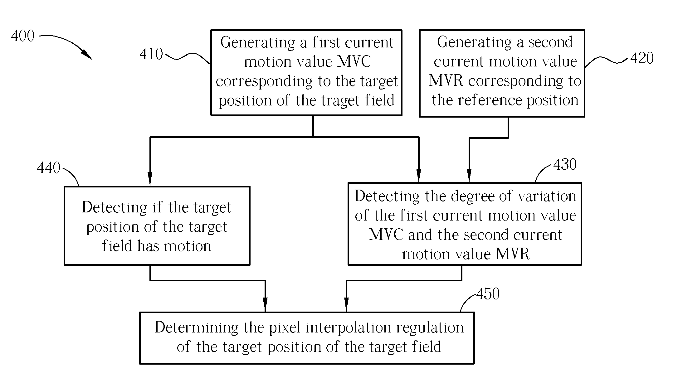
[0015] The innovative de-interlacing method of the present invention is briefly stated as follows: When the image of a target position is detected and determined to have motion, namely the image of the target position is not a “still” image, if the image corresponding to the target position meets certain specific image feature condition, then according to the de-interlacing method of the present invention an inter-field interpolation is performed to generate the pixel value of the target position.

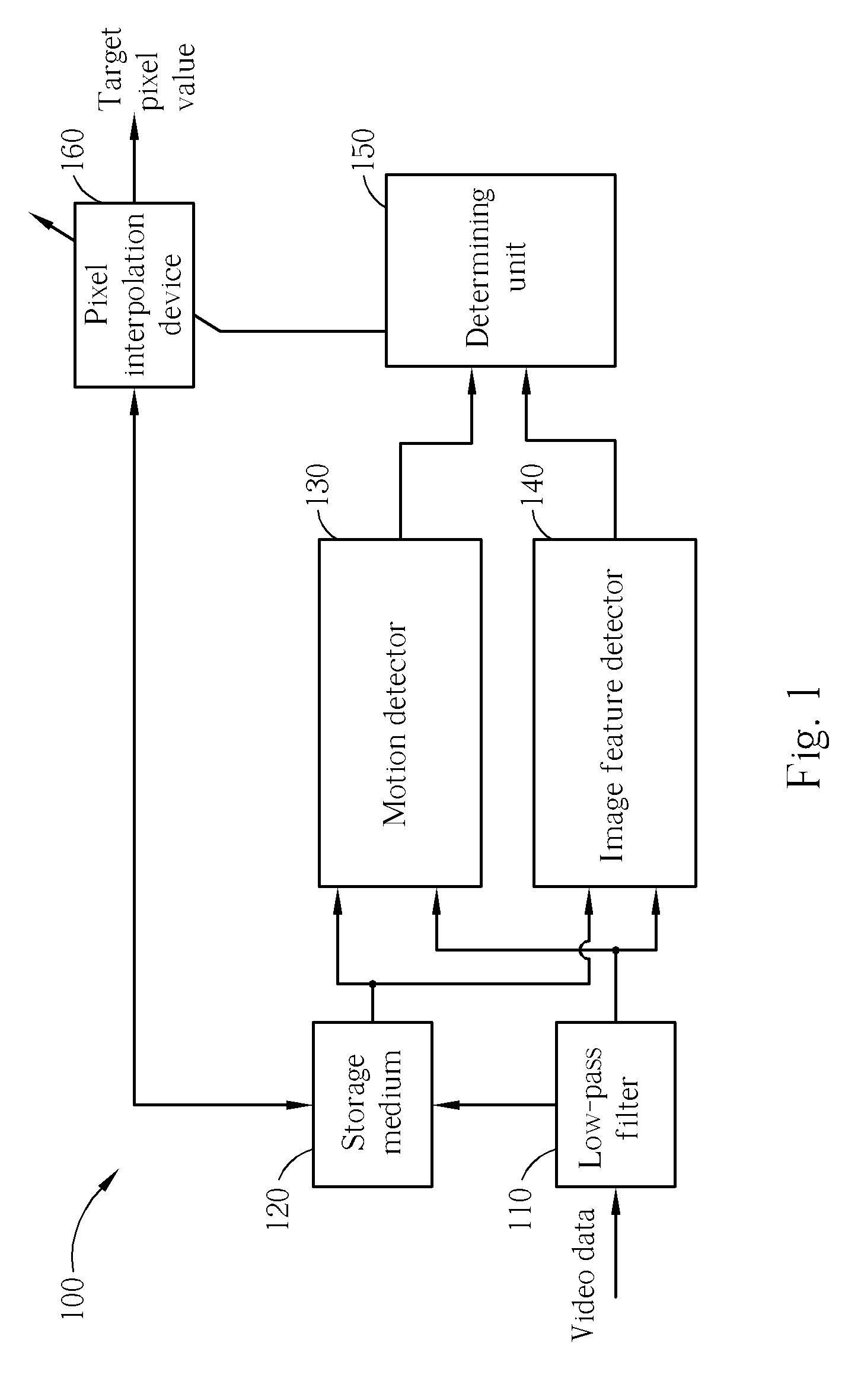
[0016] Please note that, the de-interlacing method and related apparatus disclosed below is suitable for various kinds of applications of motion adaptive de-interlacing and motion compensation de-interlacing. In addition, the term “pixel value” as used herein can be the luminance of the pixel, the chrominance of the pixel, or other values well known in or later introduced to the art that are available to process a de-interlacing operation.

[0017] Please refer to FIG. 1. FIG. 1 is a block d...


PUM


Abstract

A de-interlacing method for generating a pixel value of a target position of an output frame corresponding to a target field is disclosed. The de-interlacing method includes: generating a first motion value corresponding to the target position of the target field; determining whether the target position of the target field has motion; determining if image corresponding to the target position meets a predetermined condition; generating at least a second motion value, wherein each second motion value corresponds to a reference position of the target position; and according to the first motion value, the second motion value, and the result of the motion determining step, performing either an inter-field interpolation or an intra-field interpolation to generate the pixel value of the target position of the output frame.

Description

BACKGROUND OF THE INVENTION [0001] 1. Field of the Invention [0002] The invention relates to image processing techniques, and more particularly, to de-interlacing methods and related apparatuses. [0003] 2. Description of the Prior Art [0004] Typically, video display technology is divided into two categories. The first category is called interlaced scan and the second category is called progressive scan. Traditionally the interlaced scan technology refers the process of how to display an image frame according to two fields which are respectively formed by odd and even scan lines of the image frames. The progressive scan is also known as a non-interlaced scan, which refers to the combination of two fields into one frame, and then subsequently scanning all the scan lines of the frame with double horizontal scan frequency to improve the image quality. [0005] When displaying interlaced image data on a progressive scan type device, it is necessary to perform a de-interlacing operation. Us...

Claims


Application Information

Patent Timeline
IPC IPC(8): H04N11/20H04N7/01
CPCH04N5/144H04N7/0142H04N7/0137H04N7/012
Inventor CHAO, PO-WEI
Owner REALTEK SEMICON CORP
Features
  • R&D
  • Intellectual Property
  • Life Sciences
  • Materials
  • Tech Scout
  • Unparalleled Data Quality
  • Higher Quality Content
  • 60% Fewer Hallucinations
Learn More