Discharge valve structures for a scroll compressor having a separator plate

a technology of separator plate and discharge valve, which is applied in the direction of liquid fuel engines, machines/engines, rotary piston liquid engines, etc., can solve the problems of difficult mounting of the discharge valve within the separator plate, relatively complex and difficult discharge valve, and the boss is not adequately sealed relative to the separator plate, etc., to achieve the effect of rapid valve closing

Inactive Publication Date: 2006-10-12
SCROLL TECH
View PDF23 Cites 38 Cited by
  • Summary
  • Abstract
  • Description
  • Claims
  • Application Information

AI Technical Summary

Benefits of technology

The invention is a simplified discharge valve unit that is mounted through an opening in a separator plate. It is designed to quickly close at compressor shutdown to prevent refrigerant from leaking. The valve is held in place by a valve stop that is force-fit into a boss on the non-orbiting scroll. The valve stop includes flow passages to allow refrigerant to flow into a central portion of the valve stop, which helps to quickly close the valve. This design simplifies the manufacturing process and reduces the likelihood of leaks, which can improve the efficiency and reliability of the compressor.

Problems solved by technology

The technical problem addressed in this patent text is the difficulty and complexity of mounting a discharge valve in a scroll compressor. In the prior art, the boss where the valve is mounted is not adequately sealed relative to the separator plate, which causes leakage and reduces efficiency. The present invention provides a simpler solution for mounting the valve within the separator plate to improve efficiency and performance.

Method used


Image

  • Discharge valve structures for a scroll compressor having a separator plate
  • Discharge valve structures for a scroll compressor having a separator plate
  • Discharge valve structures for a scroll compressor having a separator plate

Examples


Embodiment Construction

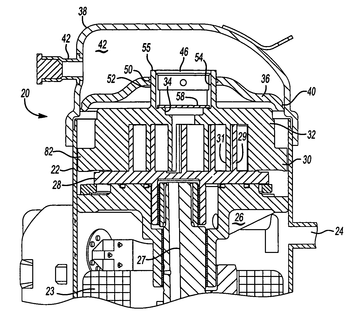
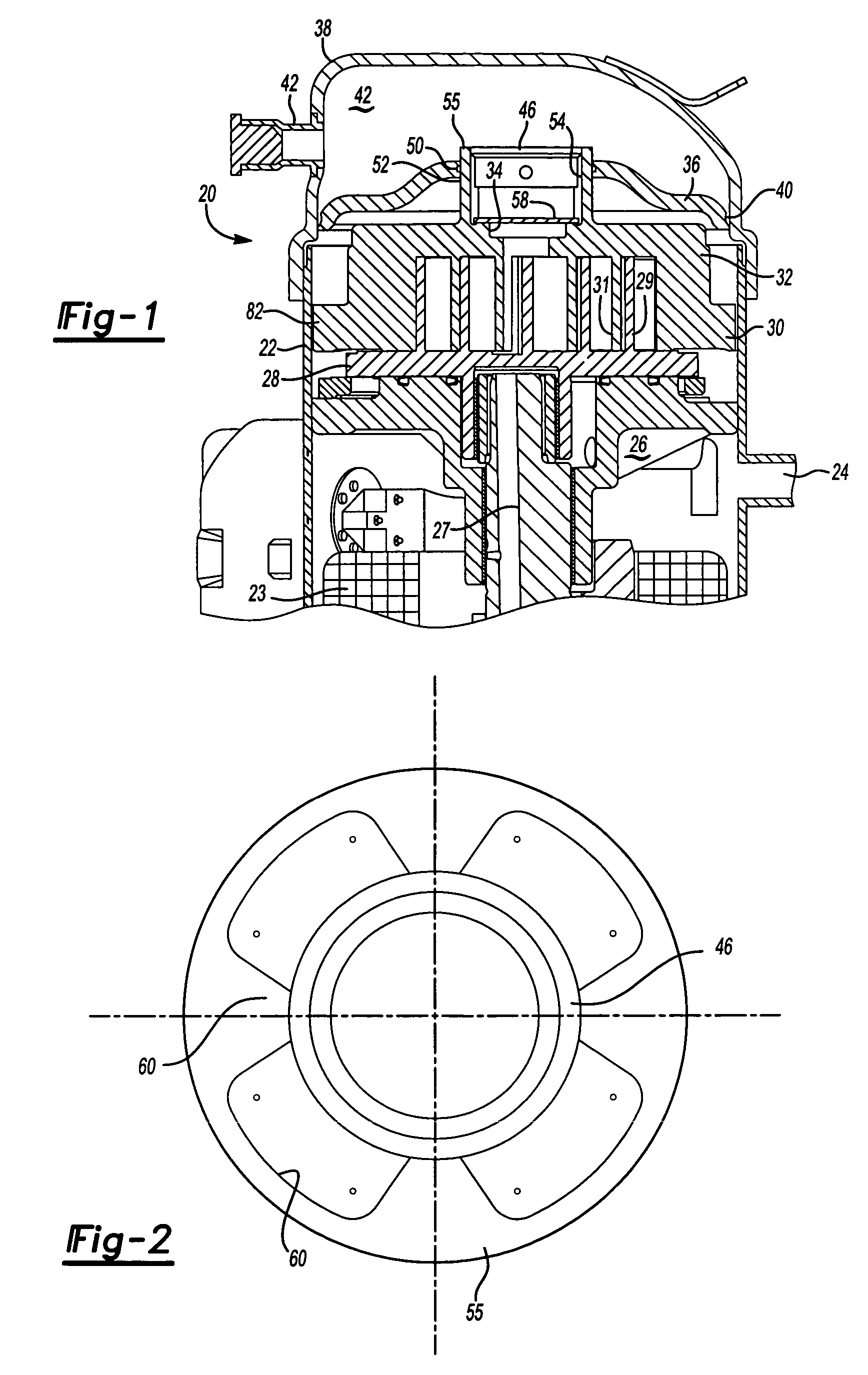
[0010] A scroll compressor 20 is illustrated in FIG. 1. As known, a housing 22 receives an electric motor 23, and a suction tube 24 allows suction pressure refrigerant to enter a suction pressure chamber 26.

[0011] An orbiting scroll 28 is caused to orbit by a rotating shaft 27. A generally spiral wrap 29 extends from a base of the orbiting scroll. A non-orbiting scroll member 30 has a base 32 and a general spiral wrap 31 interfitting with the generally spiral wrap 29. A discharge port 34 extends through the base of the non-orbiting scroll.

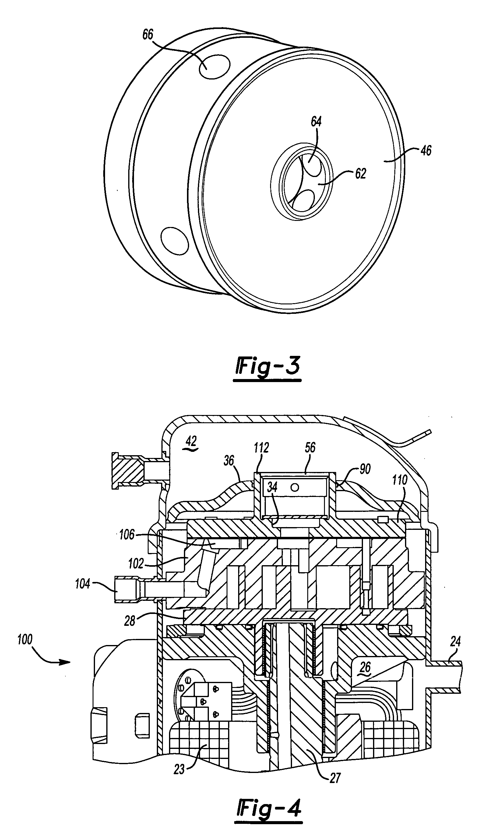
[0012] An end cap 38 receives a discharge tube 42. A separator plate 36 is sealed at 40 to the end cap 38, and defines a discharge pressure chamber 42 on one side, and the suction pressure chamber 26 on an opposed side.

[0013] A valve stop 46 is force-fit into an opening 54 in a boss 55 extending from the base 32. A seal 50 is provided to seal an interface between this boss 55 and an opening 52 in the separator plate 36. Valve stop 46 stops movem...


PUM


Abstract

A discharge valve is incorporated into a scroll compressor, and in a boss from a non-orbiting scroll. A valve stop is mounted in the boss, and the boss is sealed within an opening in a separator plate. The present invention provides a discharge valve within a scroll compressor having a separator plate while providing a more simplified construction over the prior art.

Description


Claims


Application Information

Patent Timeline
Owner SCROLL TECH
Why Eureka
Try Eureka