

Structure for mounting ultrasonic sensor on mounting member
- Summary
- Abstract
- Description
- Claims
- Application Information
AI Technical Summary
Benefits of technology
Problems solved by technology
Method used
Image

Examples
first embodiment
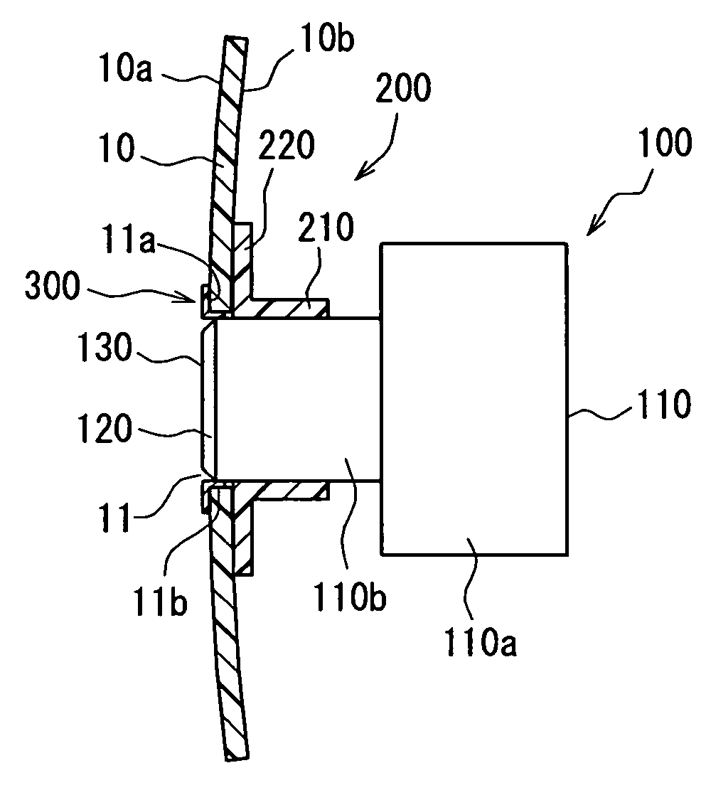
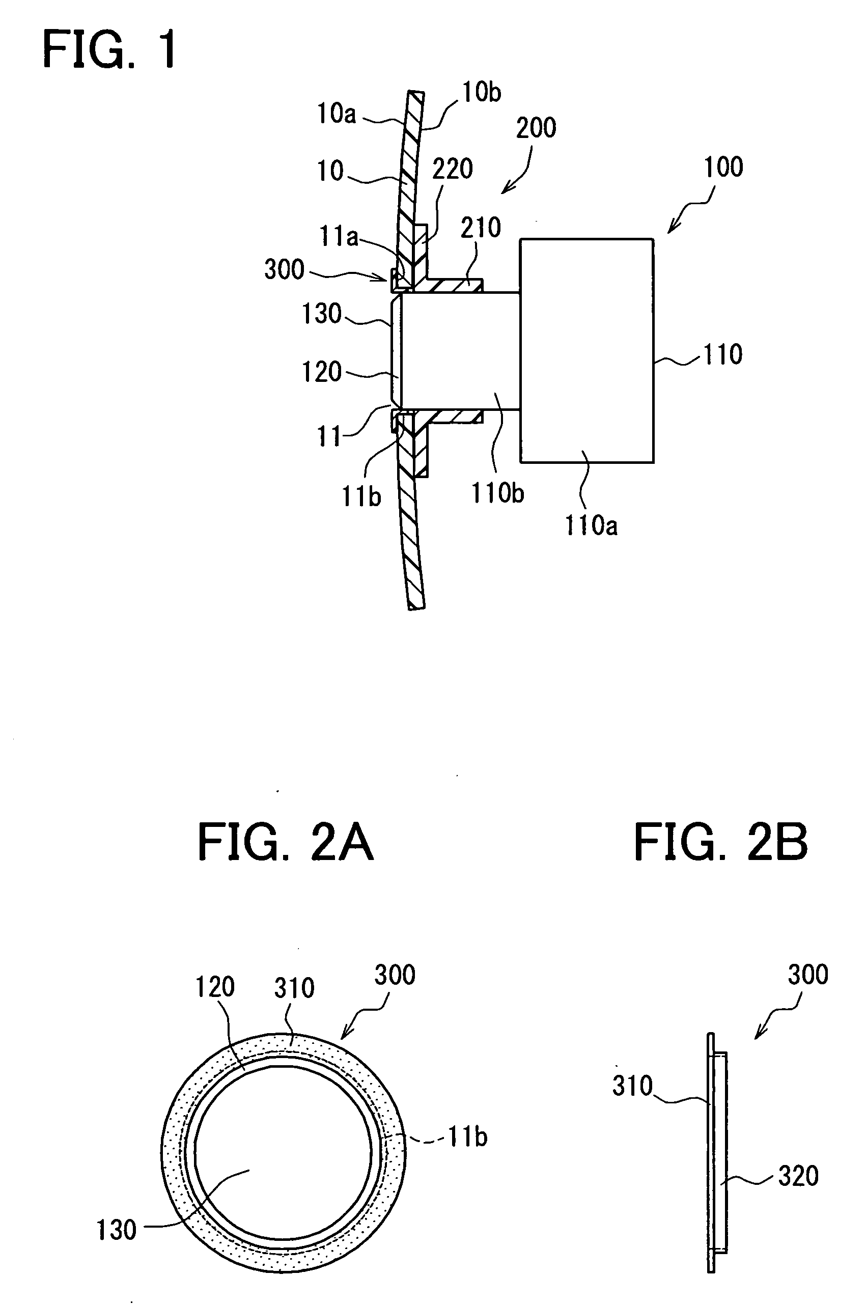
[0030] the present invention will be described with reference to FIGS. 1-3. An ultrasonic sensor 100 is mounted on a bumper of an automotive vehicle in this embodiment. The ultrasonic sensor 100 may be mounted on a front bumper or a rear bumper for serving as a corner sonar or a back sonar. The bumper serves as a mounting member 10 on which the ultrasonic sensor 100 is mounted.
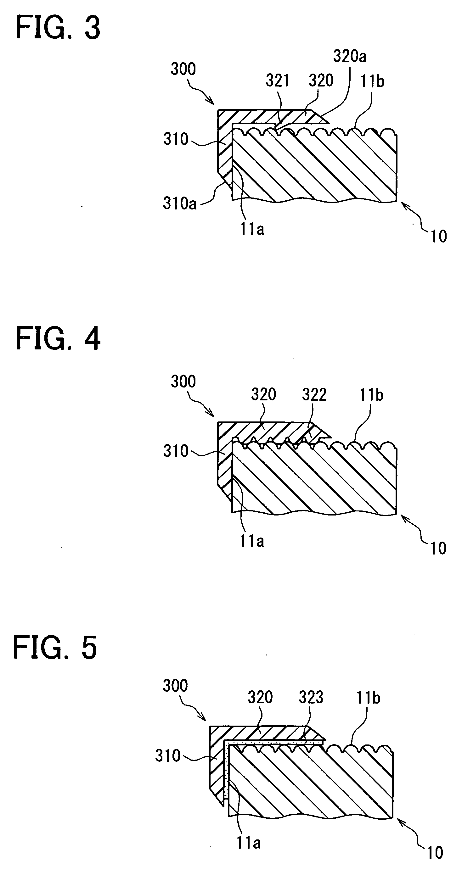
[0031] The mounting member 10 is made of synthetic resin such as urethane resin. A through-hole 11 is formed in the mounting member 10, and ultrasonic sensor 100 is inserted into the through-hole 11 and fixed to the mounting member 10 by a fixing member 200, so that a vibrating front surface 130 of the ultrasonic sensor is exposed to a front side of the mounting member 10. A front periphery 11a of the through-hole 11 is covered with a masking member 300. The ultrasonic sensor 100 includes a vibrator for transmitting ultrasonic waves toward obstacles in front of a vehicle (or toward a back side of a vehicle) an...
PUM
 Abstract
Description
Claims
Application Information