
Central current share coordinator, method of current sharing and battery plant employing the same

Active Publication Date: 2006-10-19
ABB POWER ELECTRONICS INC
View PDF3 Cites 3 Cited by
  • Summary
  • Abstract
  • Description
  • Claims
  • Application Information

AI Technical Summary

Problems solved by technology

The failure of such a system, due to either an equipment breakdown or a loss of power, is generally unacceptable since it would result in a loss of millions of voice and data communications along with its corresponding revenue.
However, the two types of rectifier systems do not provide a common current share, either by physical bus or otherwise, and are not currently able to actively current share.

Method used


Image

  • Central current share coordinator, method of current sharing and battery plant employing the same
  • Central current share coordinator, method of current sharing and battery plant employing the same
  • Central current share coordinator, method of current sharing and battery plant employing the same

Examples


Embodiment Construction

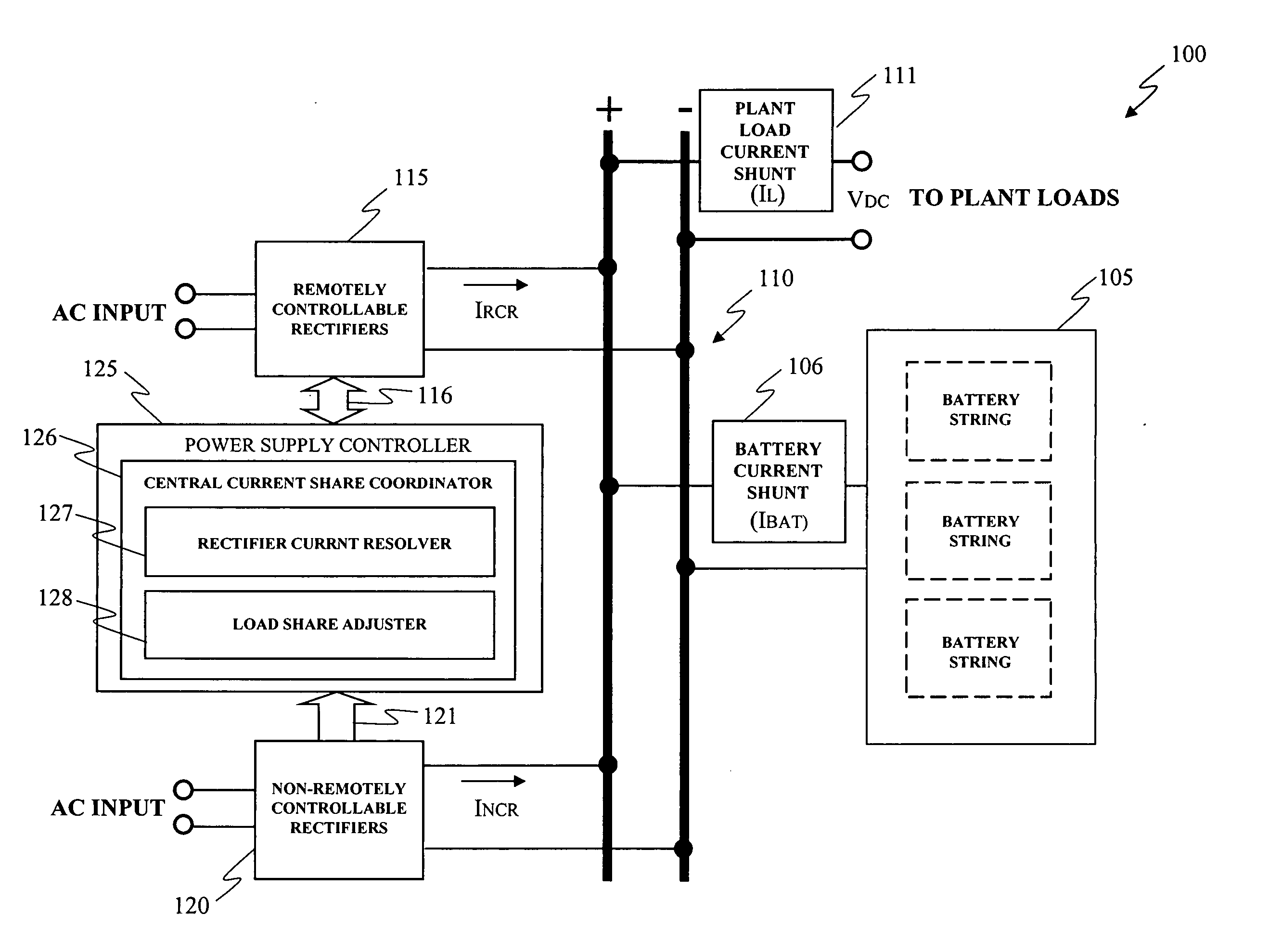
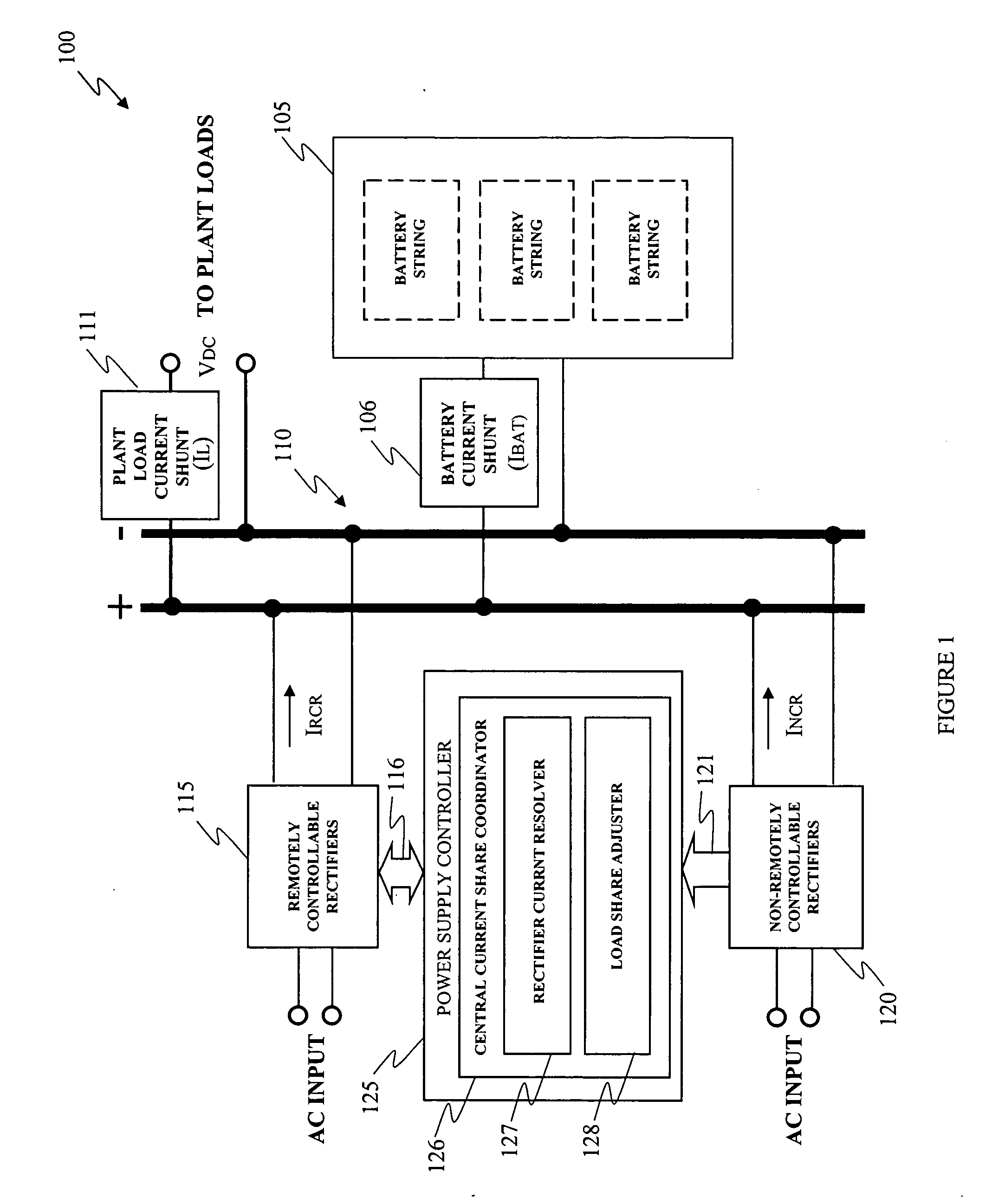
[0015] Referring initially to FIG. 1, illustrated is a block diagram of an embodiment of a battery plant, generally designated 100, constructed in accordance with the principles of the present invention. The battery plant includes a collection of battery strings 105, associated with a battery current IBAT and coupled to an output bus 110 having positive and negative conductors, that provides a plant load current IL to battery plant loads. The battery plant 100 also includes remotely controllable rectifiers 115 and non-remotely controlled rectifiers 120 that are directly connected to the output bus 110. They convert input AC power into a DC output voltage for the output bus 110 and also provide a remotely controllable rectifier output current IRCR and a non-remotely controlled rectifier output current INCR to the output bus 110, respectively.

[0016] The battery plant 100 further includes a power supply controller 125 that is coupled to the remotely controllable rectifiers 115 employi...


PUM


Abstract

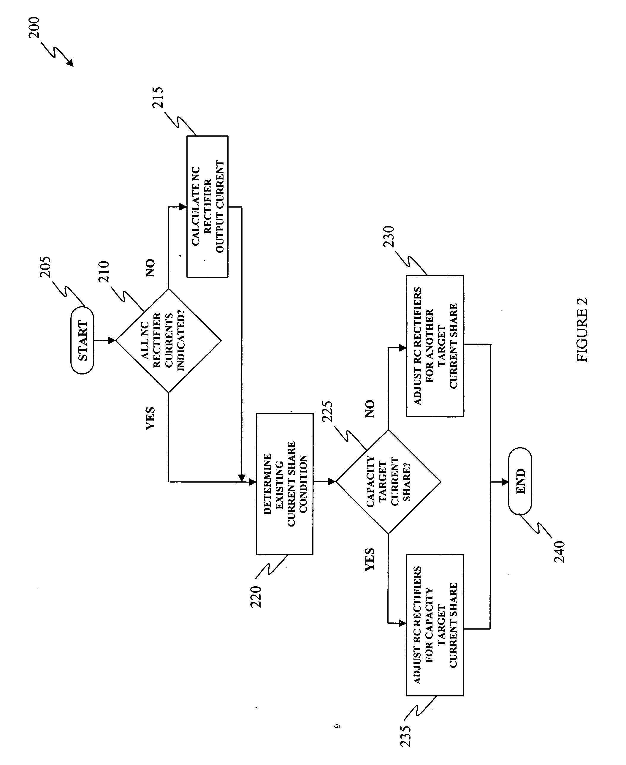
The present invention provides a central current share coordinator for use with remotely and non-remotely controllable rectifiers coupled to an output bus. In one embodiment, the central current share coordinator includes a rectifier current resolver configured to determine an existing current share condition for the remotely and non-remotely controllable rectifiers. Additionally, the central current share coordinator also includes a load share adjuster coupled to the rectifier current resolver and configured to adjust an output current of the remotely controllable rectifiers toward a target current share distribution on the output bus.

Description

TECHNICAL FIELD OF THE INVENTION [0001] The present invention is directed, in general, to power systems and, more specifically, to a central current share coordinator, a method of current sharing and a battery plant employing the coordinator or the method. BACKGROUND OF THE INVENTION [0002] Telecommunication and data switching systems are used to route tens of thousands of calls and data connections per second. The failure of such a system, due to either an equipment breakdown or a loss of power, is generally unacceptable since it would result in a loss of millions of voice and data communications along with its corresponding revenue. The traditionally high reliability of telecommunication systems, that users have come to expect, is partially based on the use of redundant equipment including power supplies. [0003] Primary power is normally supplied through commercially available AC voltage. Should the AC voltage become unavailable due to an AC power outage or the failure of one or m...

Claims


Application Information

Patent Timeline
IPC IPC(8): H02J1/12
CPCH02J1/102
Inventor HIRSCH, MARC D.BROOKE, JOHN C.DAVIS, ROY J.
Owner ABB POWER ELECTRONICS INC
Learn More