Hazard marker kit

a technology of warning devices and warning plates, which is applied in the direction of traffic signals, transportation and packaging, and ways, etc., can solve the problems of people in the vicinity of motorists, and people who are prone to burning flares, and the person charged with igniting flares risks being burned and their clothing burned

Inactive Publication Date: 2006-10-19
SAFE & SOUND SAFETY CORP
View PDF27 Cites 28 Cited by
  • Summary
  • Abstract
  • Description
  • Claims
  • Application Information

AI Technical Summary

Problems solved by technology

However, a motorist who drives past one or more flares may be temporarily blinded by their brightness, thereby endangering the motorist and people in the vicinity of the motorist.
The flare is particularly dangerous to use where an automobile collision causes a spillage of gasoline on a roadway.
Among other undesirable aspects of the flare is that a person charged with igniting the flare risks being burned and having their clothing burned.
The light cannot readily be seen outside of an immediate area where the cone is placed, particularly in poor weather conditions.
The light and the battery make the cone top heavy, thereby destabilizing the cone.
Even in the absence of the destabilizing, the cone is frequently destroyed or badly damaged when inadvertently struck by a motor vehicle.
The use of a flare on a gasoline powered boat is very dangerous since a boat in peril is not moving, thus the opportunity for gasoline vapor accumulation is high.
Further, unlike a road side situation, a flare cannot be set down safely within a boat.

Method used


Image

  • Hazard marker kit
  • Hazard marker kit
  • Hazard marker kit

Examples


Embodiment Construction

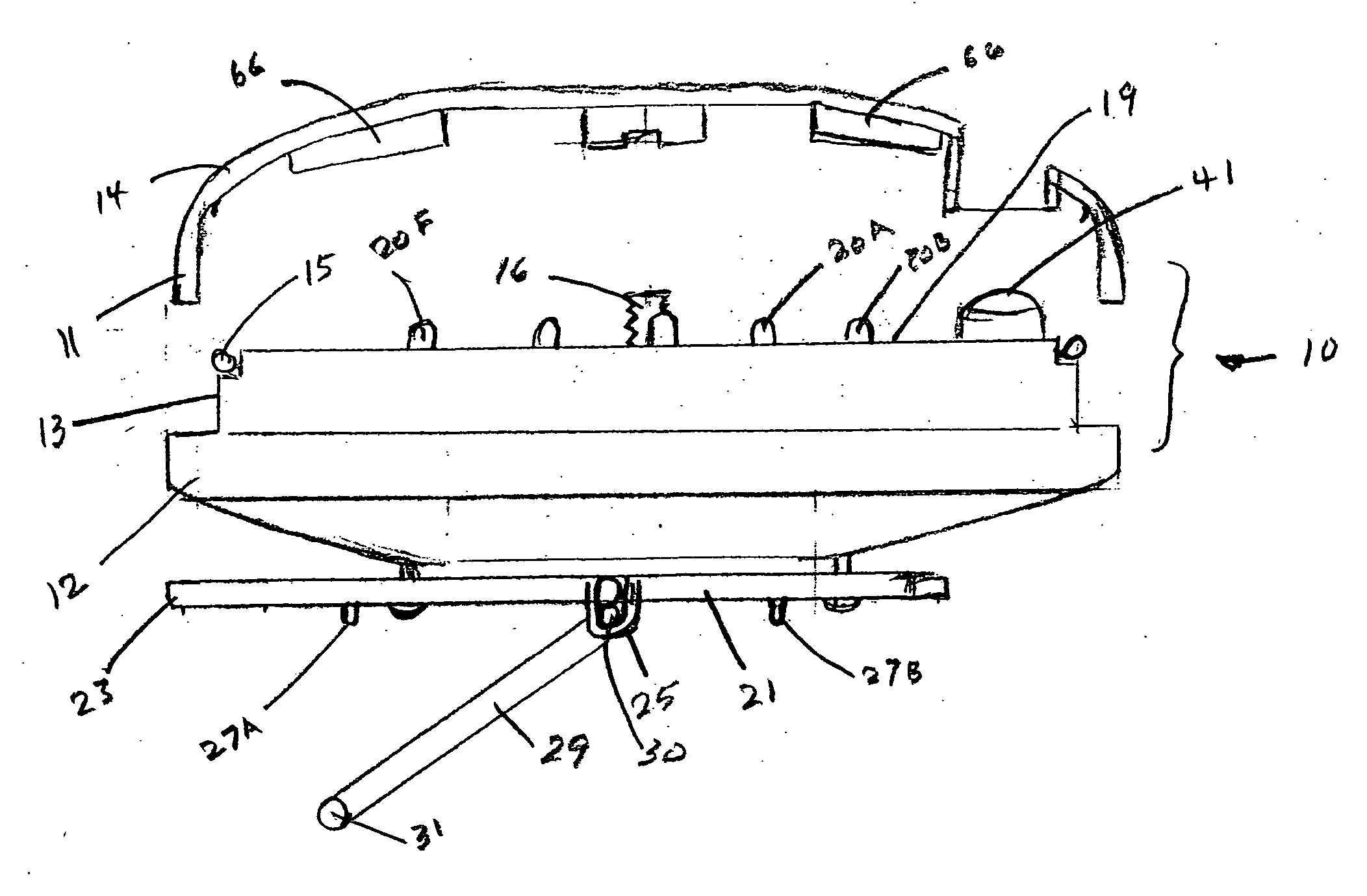
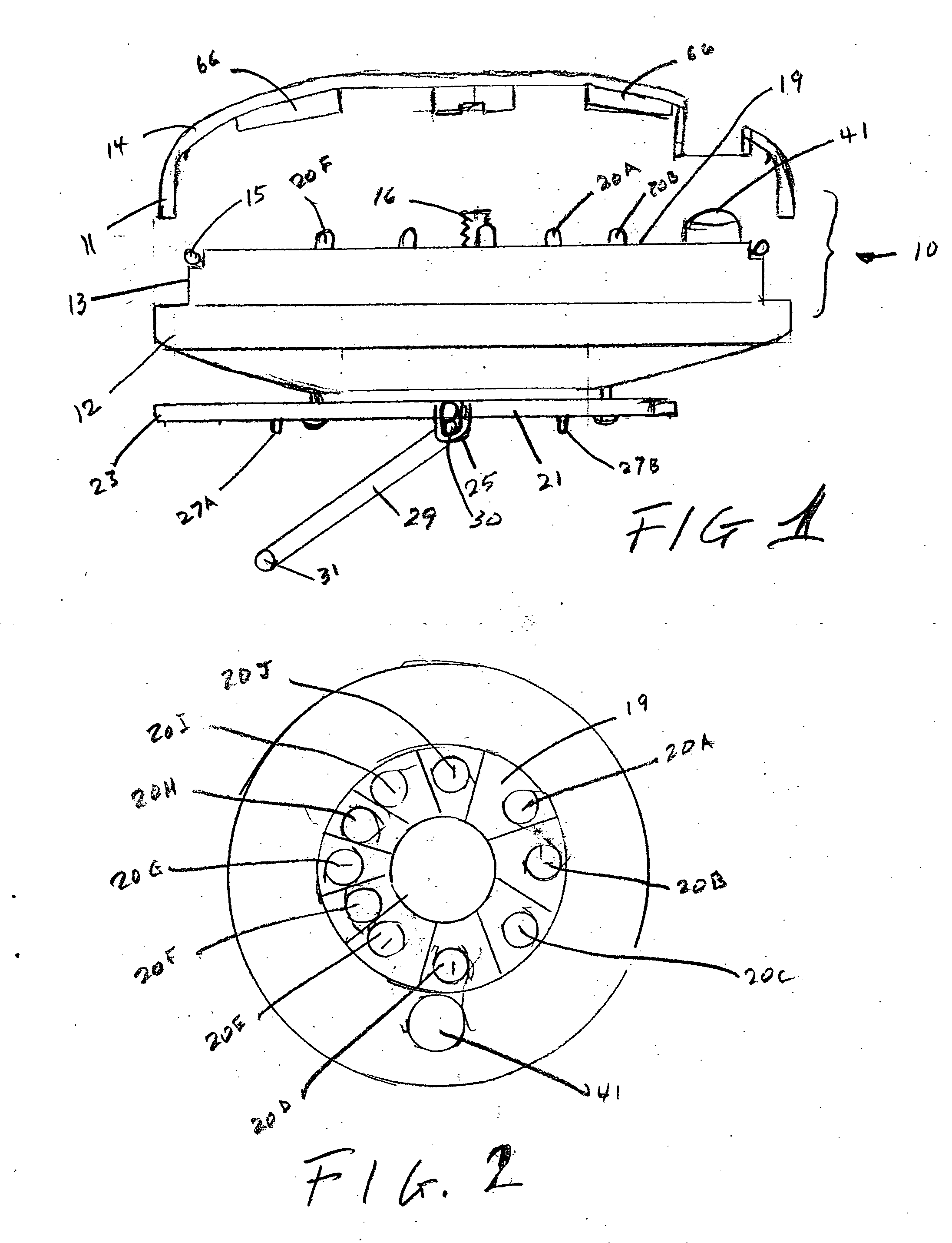
[0027] As shown in FIGS. 1 and 2, a hazard marker 10 has a general shape of a disc. The marker 10 includes a lower housing 12 and an upper housing 14 that are made from a high impact plastic. The upper housing 14 is transparent. A bolt 16 passes through the lower housing 12 and screws into the upper housing, whereby the lower housing 12 and the upper housing 14 are held together. The transparent upper housing 14 has a depending circular wall 11, shown in FIG. 1, with a diameter slightly smaller than the upstanding wall 13 of the lower housing 12. This double walled construction allows the hazard marker to be sealed against leakage. Also, a circumferential ring seal 15 supported by the upstanding wall 13 contacts upper housing 14 so that when the upper housing and the lower housing are bolted together they form a watertight joint.

[0028] Visible through the upper housing 14 is circular board 19, shown in FIG. 2, whereon LEDS 20-A through 20-J are circularly disposed. As explained her...


PUM


Abstract

A hazard marker kit has several components including a hazard light, a base for supporting the light in different angular orientations on different surfaces, a translucent cone, and a staff with attached pennant. The hazard light is housed within a disc shaped high impact plastic housing, an upper portion of which is transparent. A plurality of LEDs are circularly disposed proximal to the side of the upper portion. A ring counter provides signals to transistors that sequentially drive the LEDs. Excitation provided to the ring counter is controlled to cause a desired current through the LEDs to simulate a rotating beacon, a flashing beacon or a continuous light.

Description

BACKGROUND OF THE INVENTION [0001] 1. Field of Invention [0002] This invention is in the general field of warning devices and, more particularly, is a hazard marker kit that provides an aimed illumination device and accessories. [0003] 2. Description of the Prior Art [0004] A hazard marker is typically placed near a problem area created by a mishap or breakdown. Reasons for placing the marker include protection of people against injury, discouraging people from either walking or driving in the problem area, discouraging intrusion into emergency medical treatment of injuries resulting from the mishap and discouraging intrusion into clean up activity. The hazard marker may, for example, be a flare, a sequentially illuminated arrow, a message sign, a wooden barricade that carries a blinking warning light or an orange cone. [0005] The flare has an advantage of being easily visible at night. However, a motorist who drives past one or more flares may be temporarily blinded by their bright...

Claims


Application Information

Patent Timeline
Patent Type & Authority Applications(United States)
IPC IPC(8): B60Q1/26
CPCB60Q1/52E01F9/0165E01F9/0122B63B45/04E01F9/688E01F9/654E01F9/617
Inventor ALTMAN, BRADFORD
Owner SAFE & SOUND SAFETY CORP
Why Eureka
Try Eureka