
Tool holder

a tool and tool technology, applied in the field of tool holders, can solve the problems of limited size and types of tools to be held, inconvenient use, and tools that are not easily and quickly accessible, and achieve the effect of convenient access for users

Inactive Publication Date: 2006-10-19
E Z RED
View PDF18 Cites 34 Cited by
  • Summary
  • Abstract
  • Description
  • Claims
  • Application Information

AI Technical Summary

Benefits of technology

[0012] The tool holder of the present invention comprises a body and at least one holding member with at least one fastener. The body is preferably substantially elongated and has a securing member which may be substantially centered along the length of the body. The securing member is preferably fixed on the body. However, the securing member may be adjustable on the body. The at least one holding member operatively connects to the body, such as by operatively connecting or joining to or about the securing member of the body of the tool holder. The holding member is adjustable or fixed along the securing member of the body of the tool holder so that the holding member may accommodate any suitable size tool.
[0017] A further primary object of the invention is to provide a tool holder which can hold a plurality of tools and keep those tools out of a work area of a user, but within close reach and easily accessible to the user. For example, the tool holder of the invention may be placed in a tool box having slidable drawers.

Problems solved by technology

However, when stored in this manner, the tools may shift position and move around when the tool box is moved or opened, thereby the tools may not be easily and quickly accessible, especially for a person who uses the tools often, but needs the tools out of the way when not in use.
These devices, along with the devices above have various shortcomings including only being limited in the size and types of tools to be held, inconvenient to use, and cannot hold a plurality of tools in an organized manner.

Method used


Image

  • Tool holder
  • Tool holder
  • Tool holder

Examples


Embodiment Construction

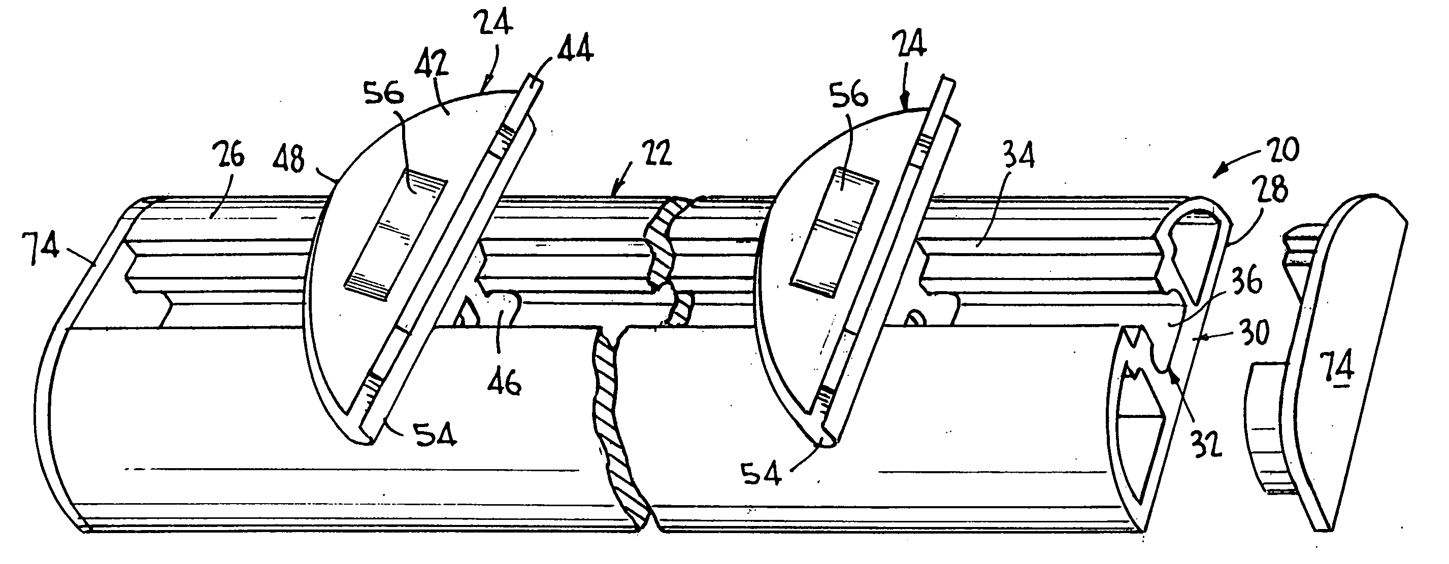
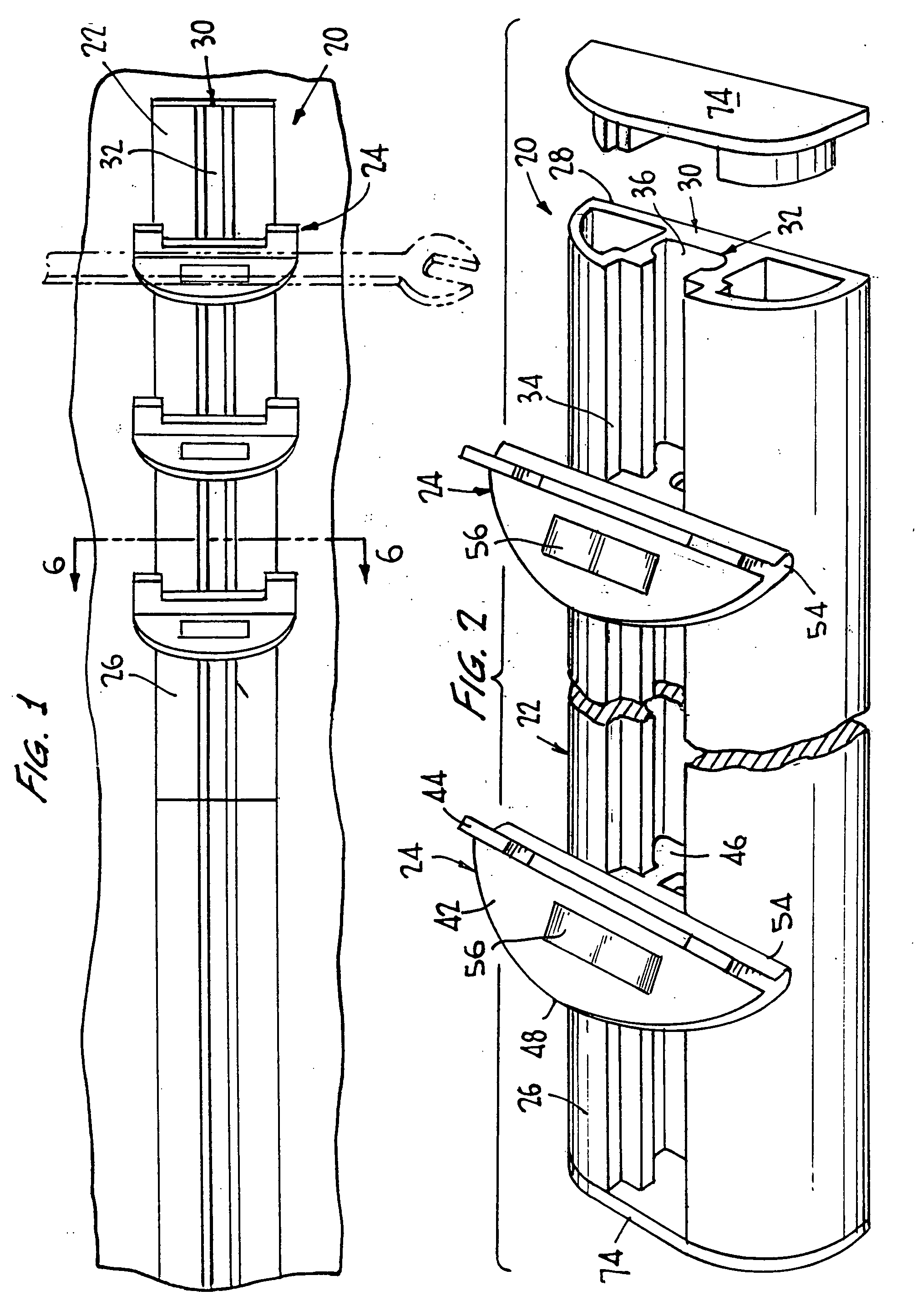
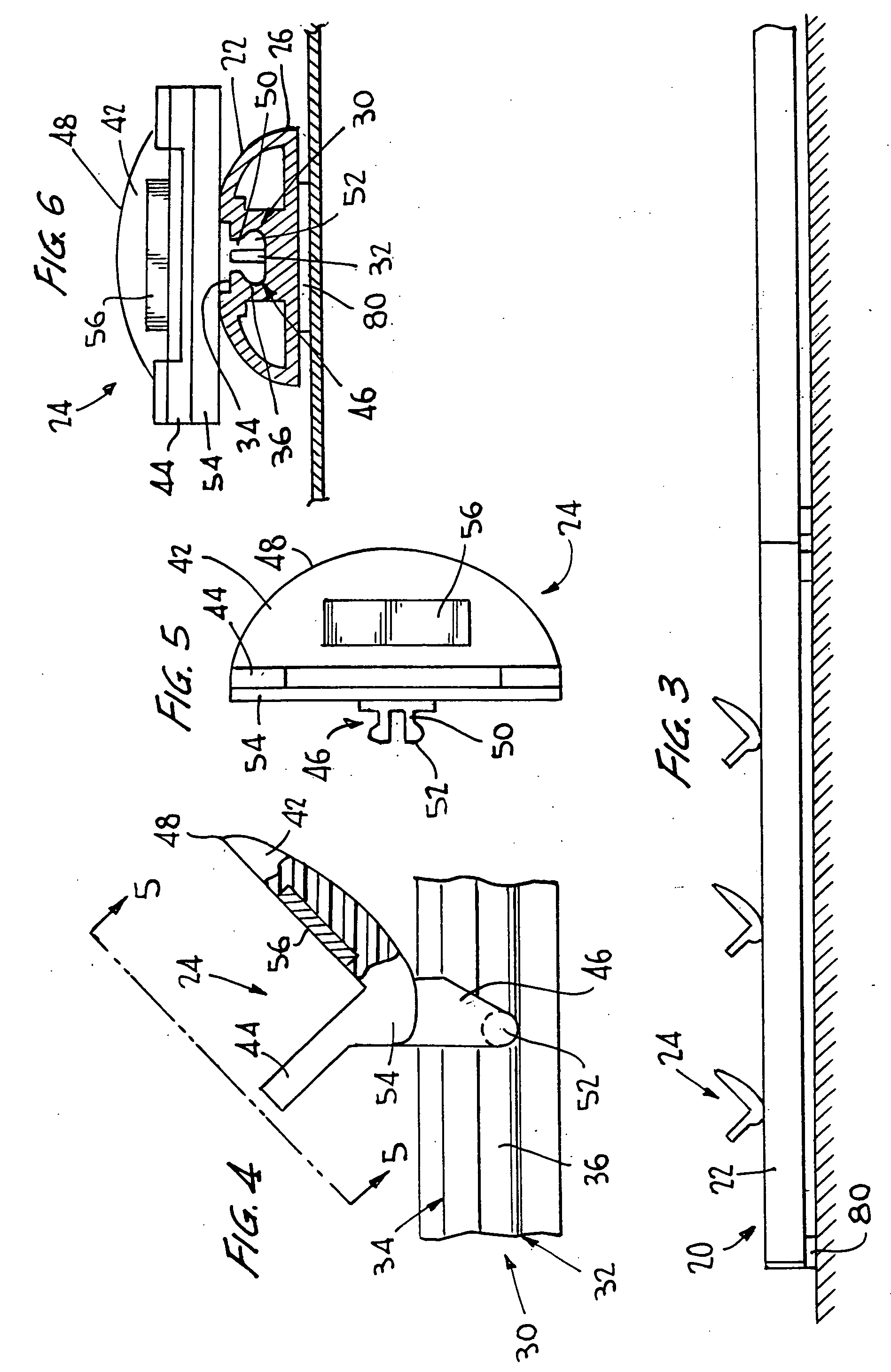
[0030] Referring to FIGS. 1-9, the tool holder 20 of the present invention comprises a body 22 and at least one holding member 24,24′ with at least one fastener therein or thereon. The body 22 is preferably substantially elongated and may be horizontally or vertically oriented when in use. A preferred embodiment of the body 22 has a first face 26 and a second face 28. The first face 26 is preferably a rounded or curved face and the second face 28 is preferably a flat face. However, the body 22 may have any suitable number of faces having any suitable shape.

[0031] A preferred embodiment of the body 22 has a securing member 30 which may be substantially centered along the length of the body 22 of the tool holder 20. The securing member 30 is used to connect or join at least one holding member 24,24′ to the body 22 of the tool holder 20. In a preferred embodiment, as shown for example in FIGS. 1-4 and 6, the securing member 30 is a channel 32 extruded from the first face 26, e.g., cur...


PUM


Abstract

A tool holder having at least one holding member with a fastener to secure at least one tool, such as a wrench or the like, on the tool holder is described. The tool holder has a body and at least one holding member with at least one fastener therein or thereon, wherein the fastener is preferably a magnet. The body is substantially elongated and has a securing member which may be substantially centered along the length of the body. The holding member(s) operatively connect to or about the body, preferably by connecting to or about the securing member of the body. The securing member is preferably a channel or a T-shaped extension member. The holding member(s) may be adjustable along the securing member or permanently fixed to the securing member such as to form a unitary tool holder so that the holding member(s) may accommodate any suitable size tool on the tool holder.

Description

FIELD OF INVENTION [0001] The present invention relates to a tool holder. More particularly, the present invention relates to a tool holder which utilizes at least one holding member, which may be adjustable or fixed, having at least one fastener to position at least one tool, such as a wrench or the like, on or to the tool holder. BACKGROUND OF THE INVENTION [0002] Various types of tools are used by many people in their daily jobs or to repair items and objects around the house or office. These tools are generally stored in a toolbox or in another storage device to keep the tools from being lost, misplaced, broken, damaged or soiled. However, when stored in this manner, the tools may shift position and move around when the tool box is moved or opened, thereby the tools may not be easily and quickly accessible, especially for a person who uses the tools often, but needs the tools out of the way when not in use. Additionally, many tool storage devices do not keep tools organized so t...

Claims


Application Information

Patent Timeline
Patent Type & Authority Applications(United States)
IPC IPC(8): B23Q3/155
CPCY10T483/1724B25H3/04
Inventor TUCKER, MARK
Owner E Z RED
Learn More