Intramedullary nail

a technology for intramedullary nail and nail, which is applied in the field of intramedullary nail, can solve the problems of greatly reduced strength of the tip of the intramedullary nail, and achieve the effects of reducing the rigidity of the nail, reducing the elasticity of the nail, and facilitating the implanting of the nail

Active Publication Date: 2006-10-19
SYNTHES USA
View PDF70 Cites 30 Cited by
  • Summary
  • Abstract
  • Description
  • Claims
  • Application Information

AI Technical Summary

Benefits of technology

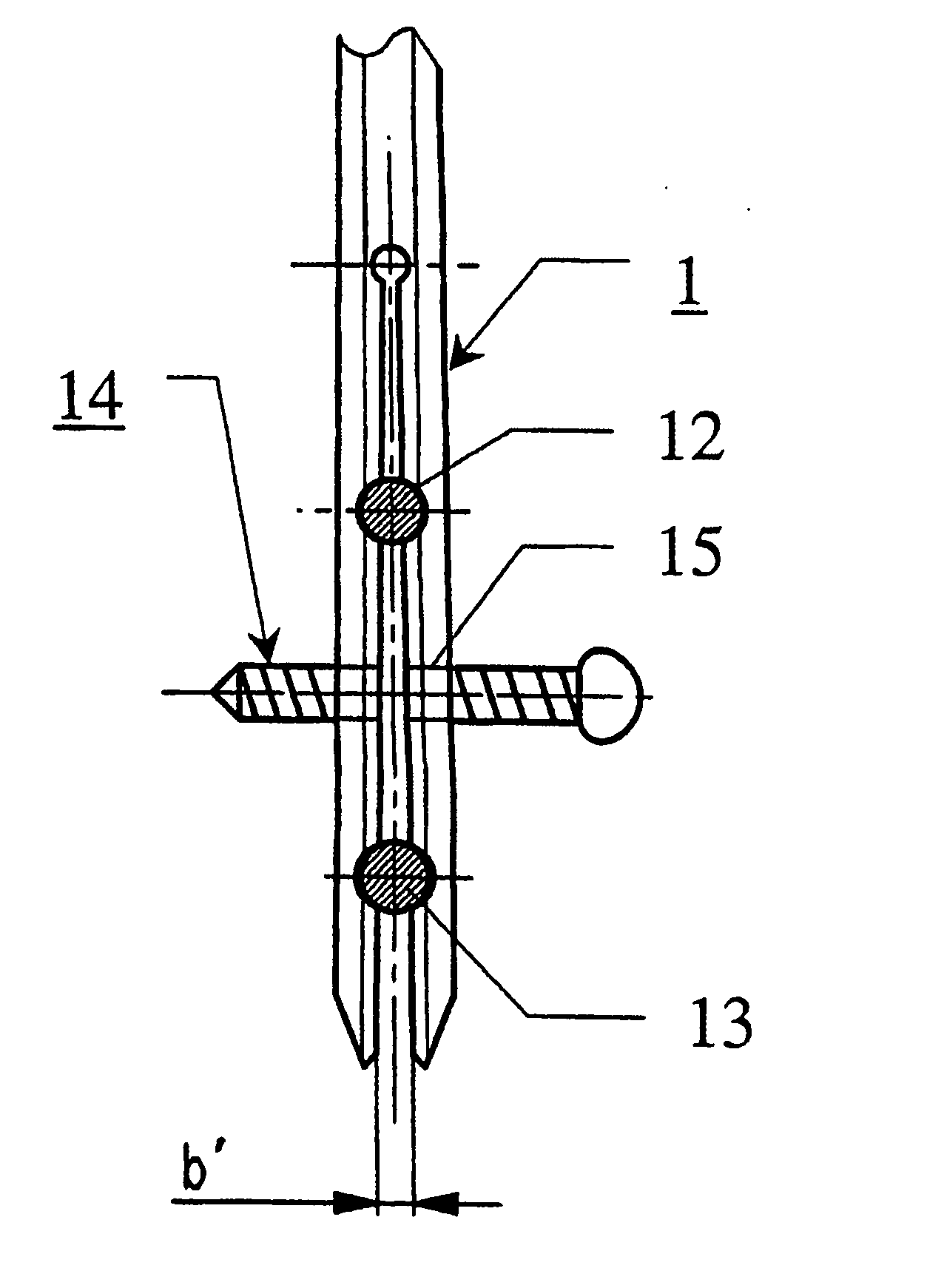
[0025] In the case of a further embodiment, the intramedullary nail has an additional locking hole, extending at right angle to the plane of the holes. This results in an increase of the rigidity of the nail after its implanting and the setting of the locking elements in the plane of both holes. The elasticity of the nail is achieved by the longitudinal slot and simplifies the implanting of the nail. However, once the nail is implanted, the return of the rigidity is desirable, particularly in the case of thin nails.

Problems solved by technology

However, the relatively wide longitudinal slot has two disadvantages: first, the strength of the tip of the intramedullary nail is greatly reduced, and second, the intramedullary nail may move axially relative to the locking screw at any time.

Method used


Image

  • Intramedullary nail
  • Intramedullary nail
  • Intramedullary nail

Examples


Embodiment Construction

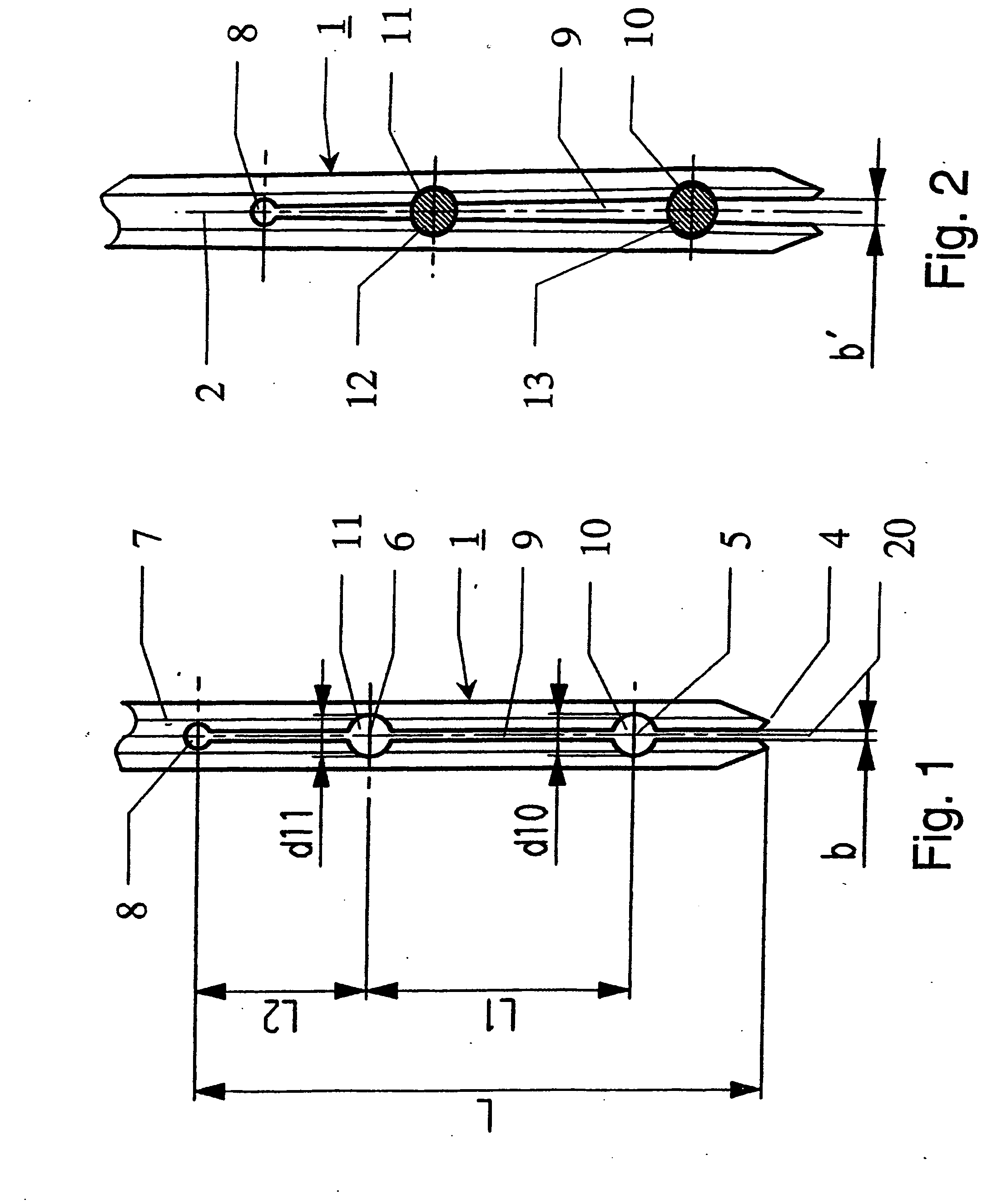
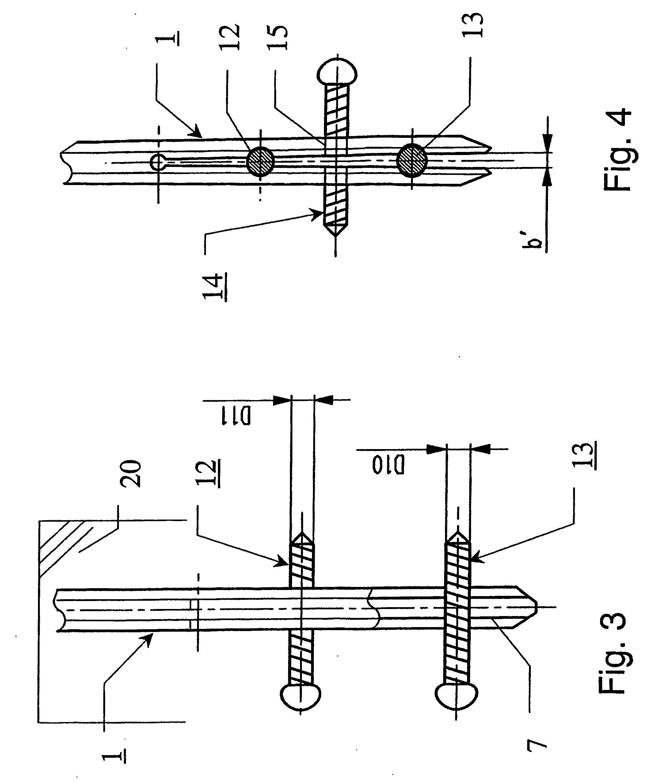
[0038] The distal end of the intramedullary nail 1, illustrated in FIG. 1, has a longitudinal axis 2, a proximal end 3, a distal end 4, as well as two holes 10,11 extending transversely to the longitudinal axis 2 and at right angles to the plane of the drawing, having diameters dlO and d11, to accommodate the locking elements 12, 13 (FIG. 2) in the form of locking screws, as well as a longitudinal slot 9 with a constant width b and a length L=(20×d10), said slot commencing at the distal end 4 and extending parallel to the longitudinal axis 2 and at right angle to the plane of the drawing. At the same time, the diameter d10 of the hole 10 situated closer to the open end of the longitudinal slot 9 is somewhat larger than the diameter d11 of the other hole 11.

[0039] In the region between the two holes 10, 11 the longitudinal slot 9 has a width b=(0.2×d10), measured in the plane of the drawing.

[0040] Both holes 10, 11 have a centre 5, 6, respectively. The longitudinal slot 9 extends f...


PUM


Abstract

The intramedullary nail has a longitudinal axis, a proximal end, a distal end, at least one hole that extends transversely to the longitudinal axis and is situated in a plane with a defined diameter to accommodate a locking element, as well as a longitudinal slot extending in the plane parallel to the longitudinal axis. In the unexpanded state of the intramedullary nail the longitudinal slot has a width b, measured perpendicularly to the plane in the region outside of the holes, said slot being maximum 0.6 times that of the smallest defined diameter of the holes.

Description

RELATED APPLICATION DATA [0001] The present application is a continuation of the U.S. National Stage designation of co-pending International Patent Application No. PCT / CH2003 / 000591, filed Aug. 29, 2003, the entire content of which is expressly incorporated herein by reference thereto.FILED OF INVENTION [0002] The invention concerns an intramedullary nail for use in orthopaedic surgery. BACKGROUND OF THE INVENTION [0003] From CH-A5 668 173 to Klaue, an intramedullary nail having a longitudinal slot at its distal end is known. This known intramedullary nail is intended to be introduced into the medullary space only after the implantation of the associated locking element (a screw or a bolt), where, with its slotted tip, it contacts the locking screw, which expands the slot such that the intramedullary nail can slide over the locking screw up to its end position. Thus, the initially set locking screw serves as a targeting aid for the intramedullary nail to be subsequently implanted. T...

Claims


Application Information

Patent Timeline
Patent Type & Authority Applications(United States)
IPC IPC(8): A61B17/56A61B17/72
CPCA61B17/7258A61B17/56A61B17/58
Inventor FRIGG, ROBERTFUHRER, MARCEL
Owner SYNTHES USA
Why Eureka
Try Eureka