Triggering apparatus for rotating-frame animal trap

a technology of rotating frame and trigger device, which is applied in the field of animal traps, can solve the problems of not being able to achieve the effect of triggering apparatus, unable to operate, and oftentimes suffering instant death of trapped animals, etc., and achieves the effect of convenient storage, packaging and transportation, and convenient transportation and re-constitution

Inactive Publication Date: 2006-10-26
HOOTMAN CLARENCE E
View PDF23 Cites 2 Cited by
  • Summary
  • Abstract
  • Description
  • Claims
  • Application Information

AI Technical Summary

Benefits of technology

[0013] Once set, actuation of the triggering device requires an animal to enter the enclosure through its entryway, and consequently through the passageway of the rotating-frame trap. Actuation of the triggering device and trap cannot occur, however, unless and until the animal is capable of reaching its arm through the restricted opening of the bait container, which is notably too small for the snout of a domestic animal, such as a dog. Upon reaching for the bait, the inquisitive “paw-feeding” animal will pull the trigger lever forward toward the opening of the bait container, thereby causing rotation of the release shaft. This, in turn, rotates the release dog, thus freeing the trigger gate which holds the detent actuating shaft and detent member in closed position. With the detent member free to rotate to an open position, the jaws of the trap are also free to rotate, and will rapidly and forcefully close upon the animal.
[0014] Preferably, as a means of convenience to facilitate storage, packaging and transportation of my new triggering device, the enclosure body may be configured from a plurality of exterior frame sections that are constructed to be collapsible. Although this may be accomplished by any known means, it is presently contemplated that selected frame sections may include snap-lock brackets designed for ease of dismantling and securing the same together to form the enclosure. With such construction, the triggering device may be readily broken down for ease of packaging and shipment, and can be readily transported and reconstructed in the field, when and where desired.

Problems solved by technology

These devices, while somewhat effective, are disadvantageous in that the trapped animal will oftentimes suffer a long and slow death, or self-mutilate its own extremities in an attempt to free itself.
Upon actuation, the jaws are intended to snap shut on the animal's spinal column at the base of the skull, thus causing instant death.
However, with this conventional triggering device, it is impossible to control the size, species, or direction of the animal entering the trap.
Consequently, domestic animals and pets, such as dogs, are frequent victims of this type trap.
The indiscriminate nature of the above conventional triggering means has been a long-standing and continuing problem that persists to this day.

Method used


Image

  • Triggering apparatus for rotating-frame animal trap
  • Triggering apparatus for rotating-frame animal trap
  • Triggering apparatus for rotating-frame animal trap

Examples


Embodiment Construction

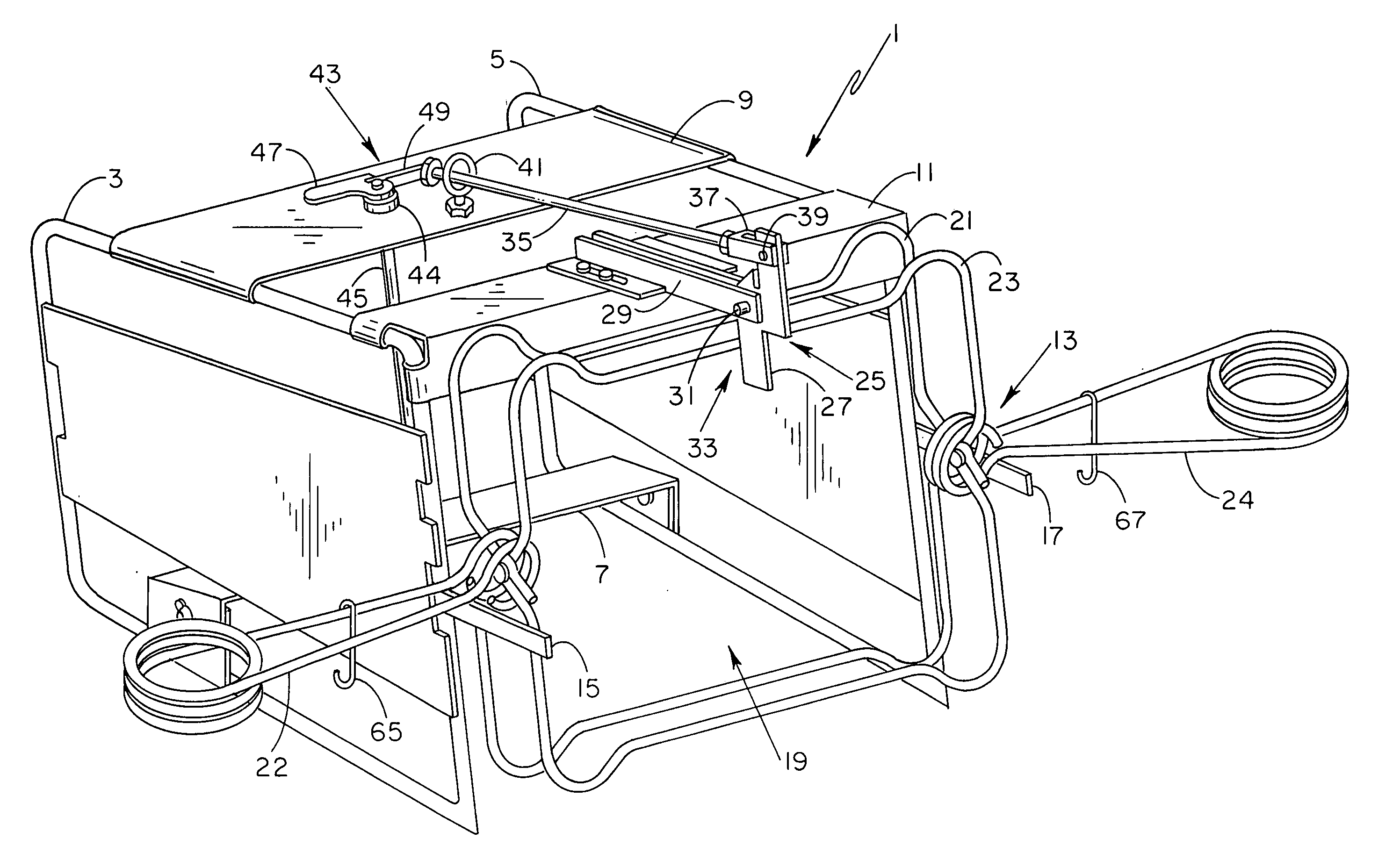
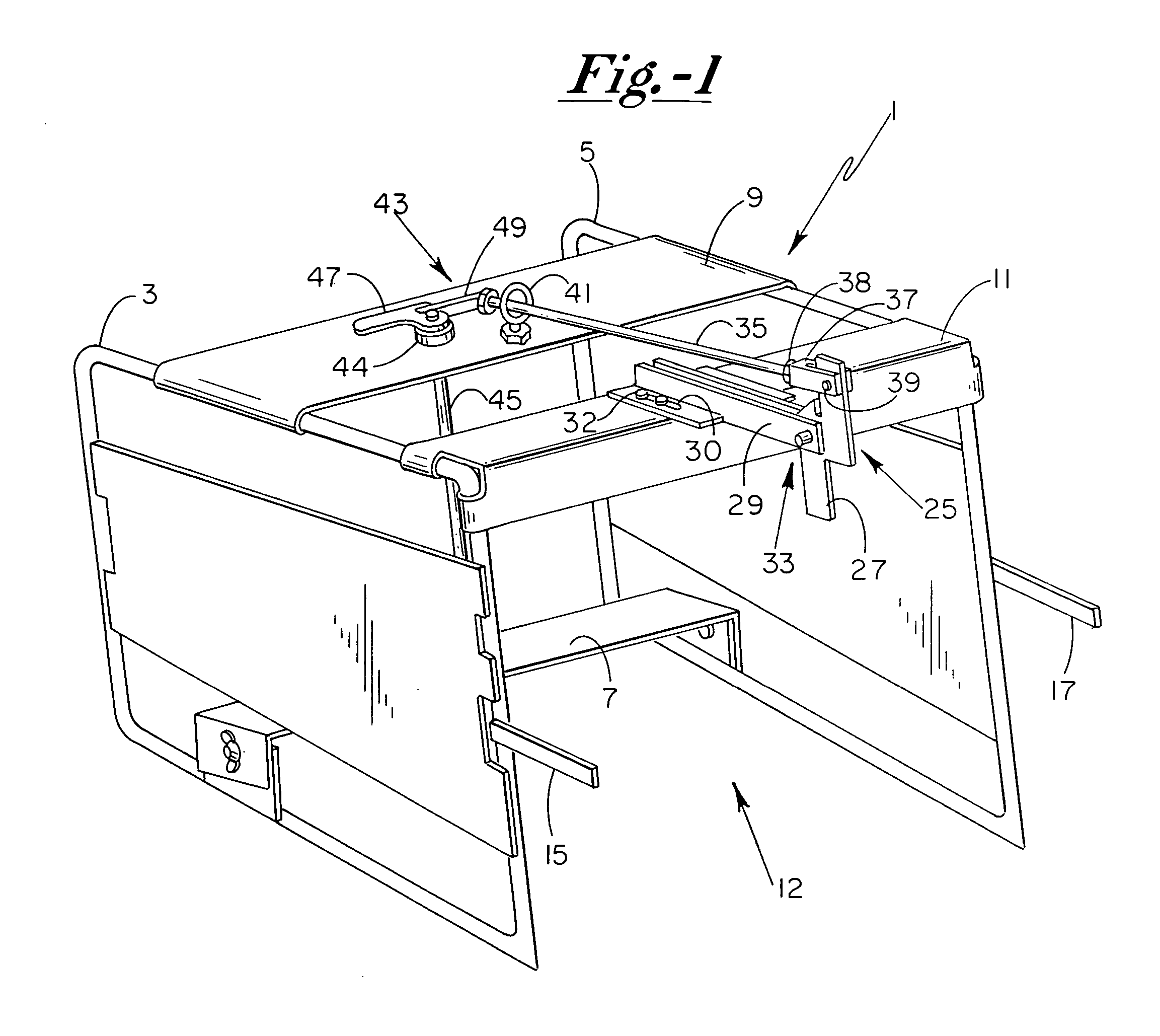
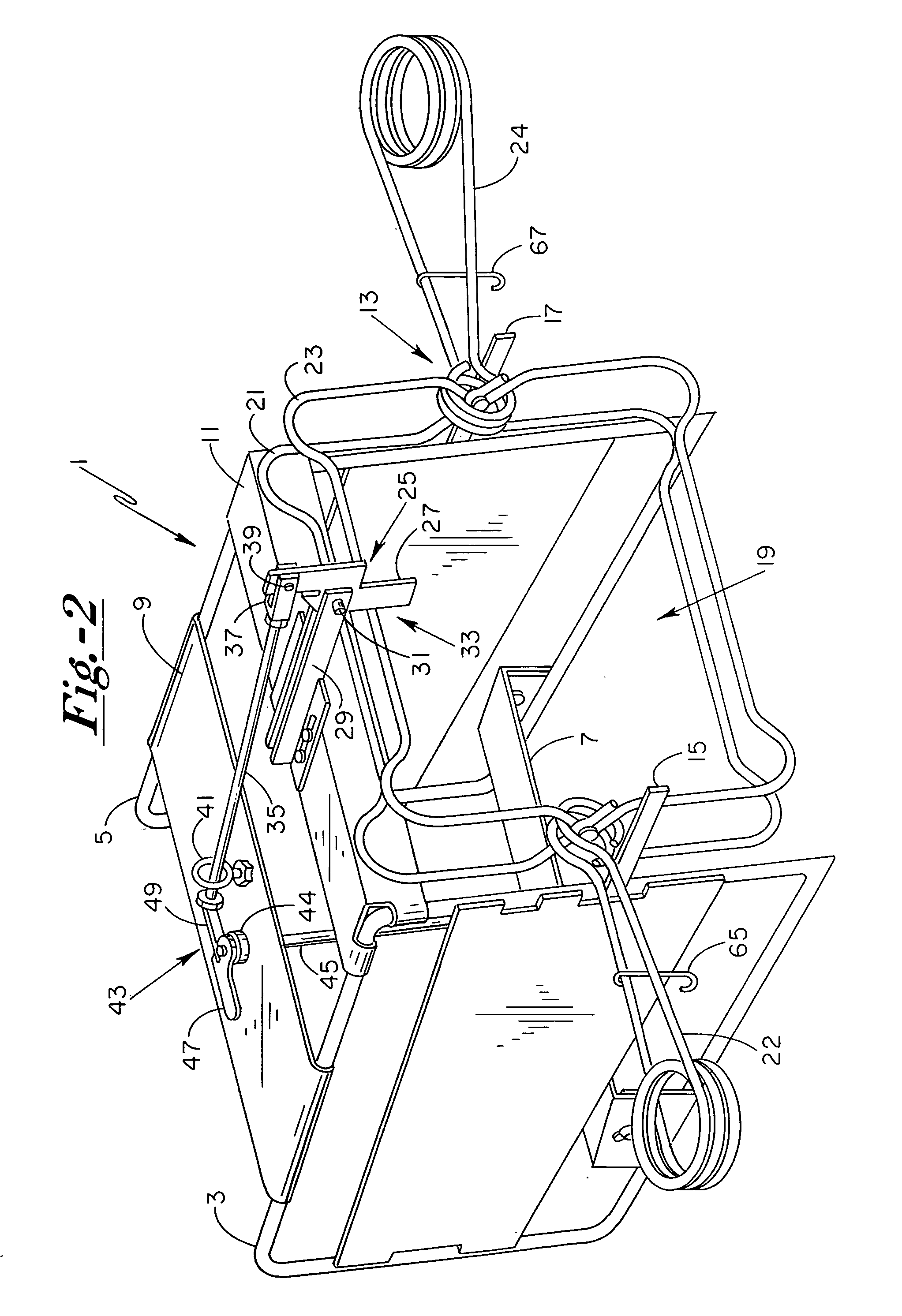
[0023] As shown in FIG. 1, and in accordance with the present invention, my improved triggering apparatus for a rotating-frame animal trap includes an outer enclosure 1 which is constructed of a pair of spaced side-body frame sections 3 and 5 that are interconnected by a lower transverse cross-panel 7 and upper transverse cross-panels 9 and 11 to define a front enclosure entryway 12. The enclosure 1 is constructed to be a stand-alone unit that is separate from the trap which it is meant to support. More specifically, as shown best in FIG. 2, the enclosure 1 includes supporting arms 15 and 17 which extend outward and forwardly from side-body frame sections 3 and 5, respectively, to support a rotating-frame animal trap 13 when the same is set in its spring-loaded firing position. When properly set, as shown in FIG. 2, the trap 13 is supported by its actuating springs 22 and 24 on the arms 15 and 17 with the passageway 19 through the trap jaws 21 and 23 positioned in general alignment ...


PUM


Abstract

A triggering apparatus for a rotating-frame animal trap including a collapsible enclosure capable of supporting the trap in set position in alignment with the enclosure entrance, the enclosure having a separate bait container mounted within its interior and a triggering lever extending within the bait container, whereupon movement of the lever within the bait container causes rotation of a release shaft that frees a catch holding the trap in set position, thereby firing the trap and pinning the animal within the trap's rotating jaws. The catch includes a detent that holds the jaws of the trap in set position against the body of the enclosure adjacent its entrance, such that the animal must pass through the set jaws of the trap in order to access the bait container. The bait container is constructed with a restricted opening of substantially smaller compass than the entrance of the enclosure so as to permit access only by a smaller animal's paw, and prevent such animals, as dogs, from triggering the trap with their snout.

Description

BACKGROUND OF THE INVENTION [0001] The present invention relates generally to the field of animal traps, and more specifically to the art of triggering devices for use in connection with so-called “instant kill” animal traps of the rotating-frame type. [0002] Many attempts have been made over the years to develop an animal trap that will effectively and humanely dispose of certain animals, such as raccoons, which continue to pester farmers and the like by destroying vegetation, poultry and other small animals. Since such animals are generally paw-feeders that use their paws to reach for and grasp their food, a number of spring-loaded “leg-hold” type trapping devices have been developed which are designed to clamp down on the leg of the animal upon triggering same. Devices of this type are disclosed in U.S. Pat. Nos. 6,658,787; 4,802,301; 4,483,093; and 4,158,929. These devices, while somewhat effective, are disadvantageous in that the trapped animal will oftentimes suffer a long and...

Claims


Application Information

Patent Timeline
Patent Type & Authority Applications(United States)
IPC IPC(8): A01M23/24
CPCA01M23/30A01M23/245
Inventor HOOTMAN, CLARENCE E.
Owner HOOTMAN CLARENCE E
Why Eureka
Try Eureka