Storm panel assembly

a panel and assembly technology, applied in the direction of shutters/movable grilles, construction, building components, etc., can solve the problems of not allowing light into the structure, heavy panels, and cumbersome handling, so as to reduce the fracturing of panels, reduce the rattling and shaking of panels, and improve the aesthetic appearance of structures.

Inactive Publication Date: 2006-10-26
TAPCO INTERNATIONAL CORPORATON
View PDF13 Cites 7 Cited by
  • Summary
  • Abstract
  • Description
  • Claims
  • Application Information

AI Technical Summary

Benefits of technology

[0010] The subject invention provides storm protection while also improving the aesthetic appearance of the structure. The storm panel assembly is relatively lightweight and can be adapted for various openings and for different structures and allows light to pass therethrough. Further, the subject invention provides the panel being able to absorb the force from debris. The locking insert secures the panel sufficiently to allow for slight play such that when the debris strikes the assembly, the panel is able to flex and repel the debris with limited or reduced fracturing of the panel. Additionally, the panel is sufficiently secured within the frame to reduce and / or prevent the panel from being torn off or from rattling and shaking during a storm.

Problems solved by technology

These storm panels are typically non-decorative and do not allow light into the structure.
The panels are heavy, awkward, and cumbersome to handle.
It is cumbersome and time intensive to mount these storm panels as the storm is approaching.
However, these large boxes are unsightly blemishes on the buildings.
These shutters are non-decorative, but are self-storing within the boxes.
However, the thermoplastic panels have a tendency to fracture or shatter as a result of the thermoplastic panels being rigidly secured to the structure.
If the panel is loosely secured to the structure, there is a likelihood that the panel may be torn off during a storm.
Additionally, even in light winds, loose panels may vibrate or rattle resulting in undesirable noise being produced.

Method used


Image

  • Storm panel assembly
  • Storm panel assembly
  • Storm panel assembly

Examples


Embodiment Construction

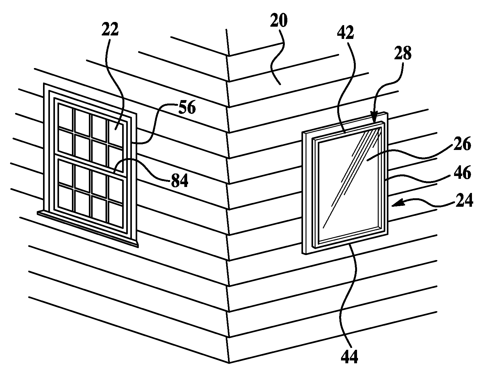
[0026] With reference to FIG. 1, an exterior front side view of a structure 20, such as a house, having openings 22 therein, such as windows, is illustrated. A storm panel assembly for storm protection is illustrated generally at 24 as covering one of the openings22. The storm panel assembly 24 provides storm protection to the opening 22, and more specifically, protects the opening 22 from items, such as debris, hail, water, wind, or the like, in a hurricane or a storm. Debris flying around may contact the storm panel assembly 24 and therefore the storm panel assembly 24 should be able to withstand wind and load forces that may be encountered.

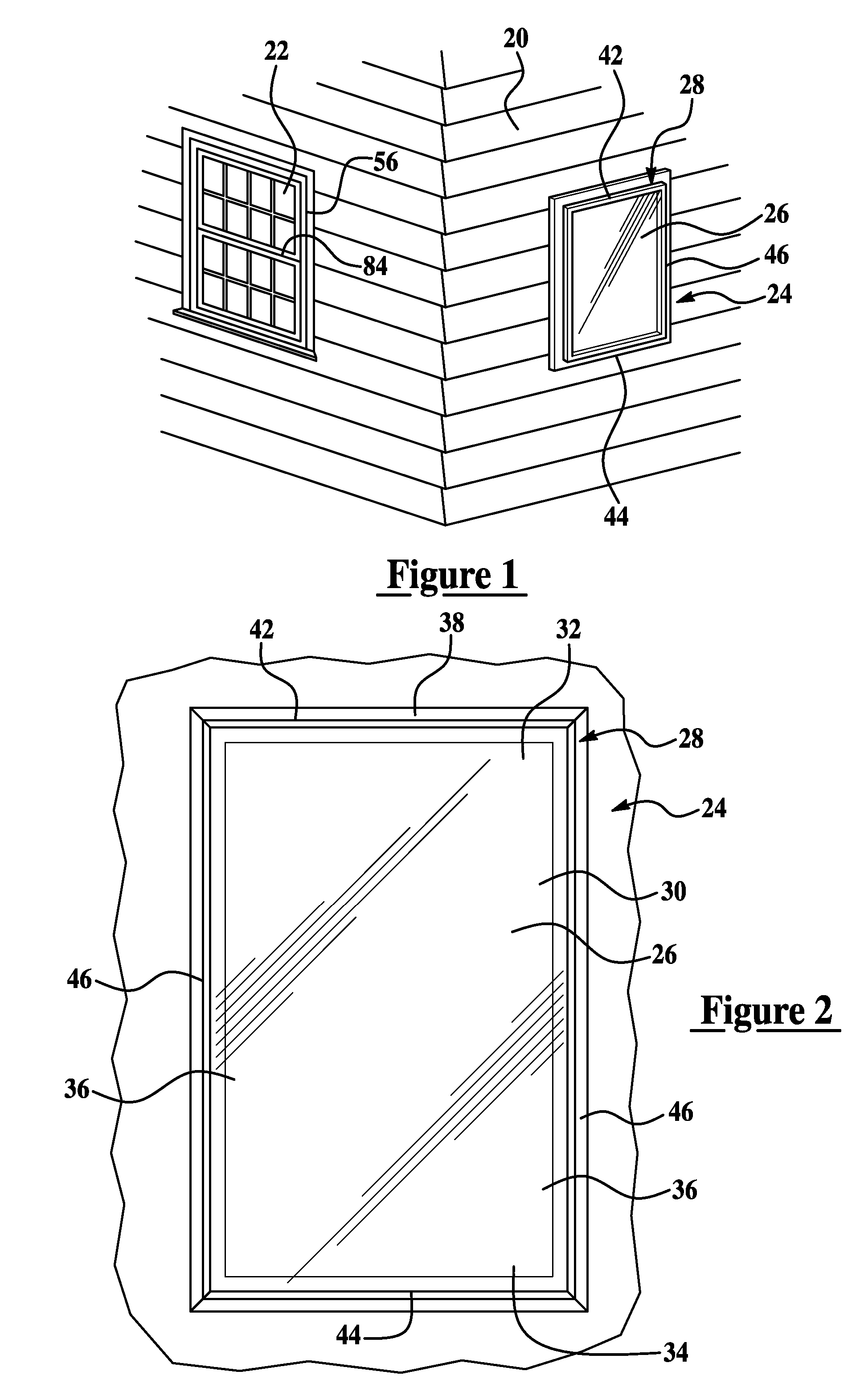
[0027] The storm panel assembly 24 comprises a panel 26 and a frame 28 for mounting to the structure 20 and for receiving the panel 26 therein. FIG. 2 illustrates the storm panel assembly 24 mounted to a wall covering an opening 22. The panel 26 has an outer periphery 30 supported by the frame 28. The panel 26 generally includes a top end 32, ...


PUM


Abstract

A storm panel assembly mounts on a structure adjacent an opening. The storm panel assembly comprises a frame having a flange for securing the frame to the structure and defines a channel having a locking tab and a first locking surface. A panel having an outer periphery is supported by the frame and a retention portion is disposed adjacent the outer periphery such that the retention portion is received within the channel. A locking insert having a second locking surface for mating with the first locking surface biases the retention portion into contact with the locking tab to secure the panel within the frame.

Description

CROSS REFERENCE TO RELATED APPLICATION [0001] This application claims the benefit of application Ser. No. 60 / 674,650 filed Apr. 25, 2005.BACKGROUND OF THE INVENTION [0002] 1. Field of the Invention [0003] The subject invention relates to a storm panel assembly, and more specifically to a storm panel assembly for providing storm protection, especially hurricane protection, that does not fracture upon impact from debris. [0004] 2. Description of the Related Art [0005] Storm panels, e.g., wood or plywood panels may be used to cover or protect windows during severe weather. These storm panels are typically non-decorative and do not allow light into the structure. The panels prevent debris from hitting and breaking the windows. Typically, the panels are large and must be manually fastened to the window frame by screws or nails. The panels are heavy, awkward, and cumbersome to handle. When there is no severe weather, the panel must be stored elsewhere, e.g., a storage shed or garage and m...

Claims


Application Information

Patent Timeline
Patent Type & Authority Applications(United States)
IPC IPC(8): E06B3/28
CPCE06B3/28E06B9/02E06B3/5842
Inventor ALLEN, CLYDE G.GREENWAY, NATHANKUTLER, BRADLOGAN, J. RICHARD
Owner TAPCO INTERNATIONAL CORPORATON
Why Eureka
Try Eureka