

Window shade lift cord apparatus
a technology for lifting cords and window shades, applied in the direction of shutters/movable grilles, door/window protective devices, wing arrangements, etc., can solve problems such as tedious process, and achieve the effect of easing the process of retracting the window shad
- Summary
- Abstract
- Description
- Claims
- Application Information
AI Technical Summary
Benefits of technology
Problems solved by technology
Method used
Image

Examples
Embodiment Construction
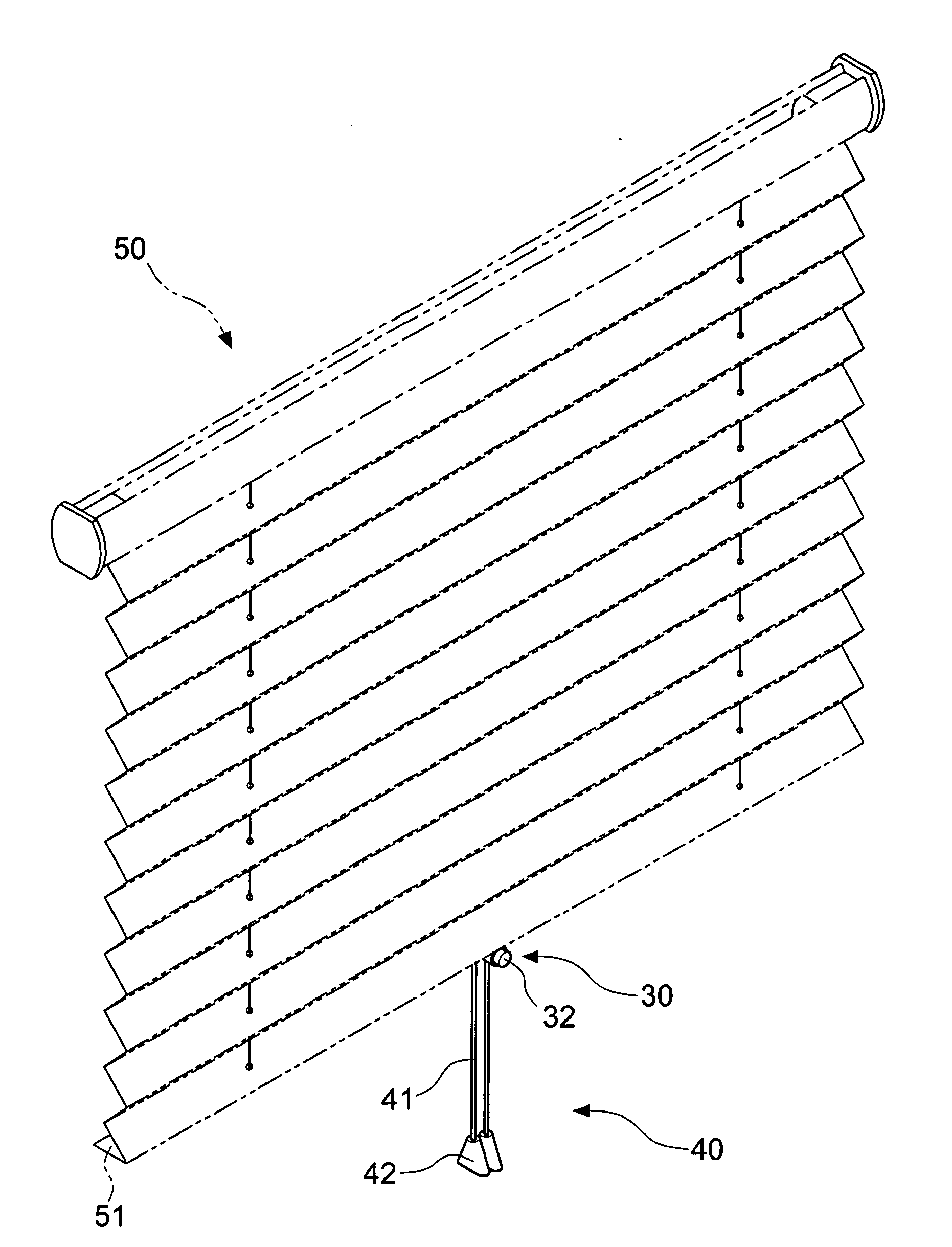
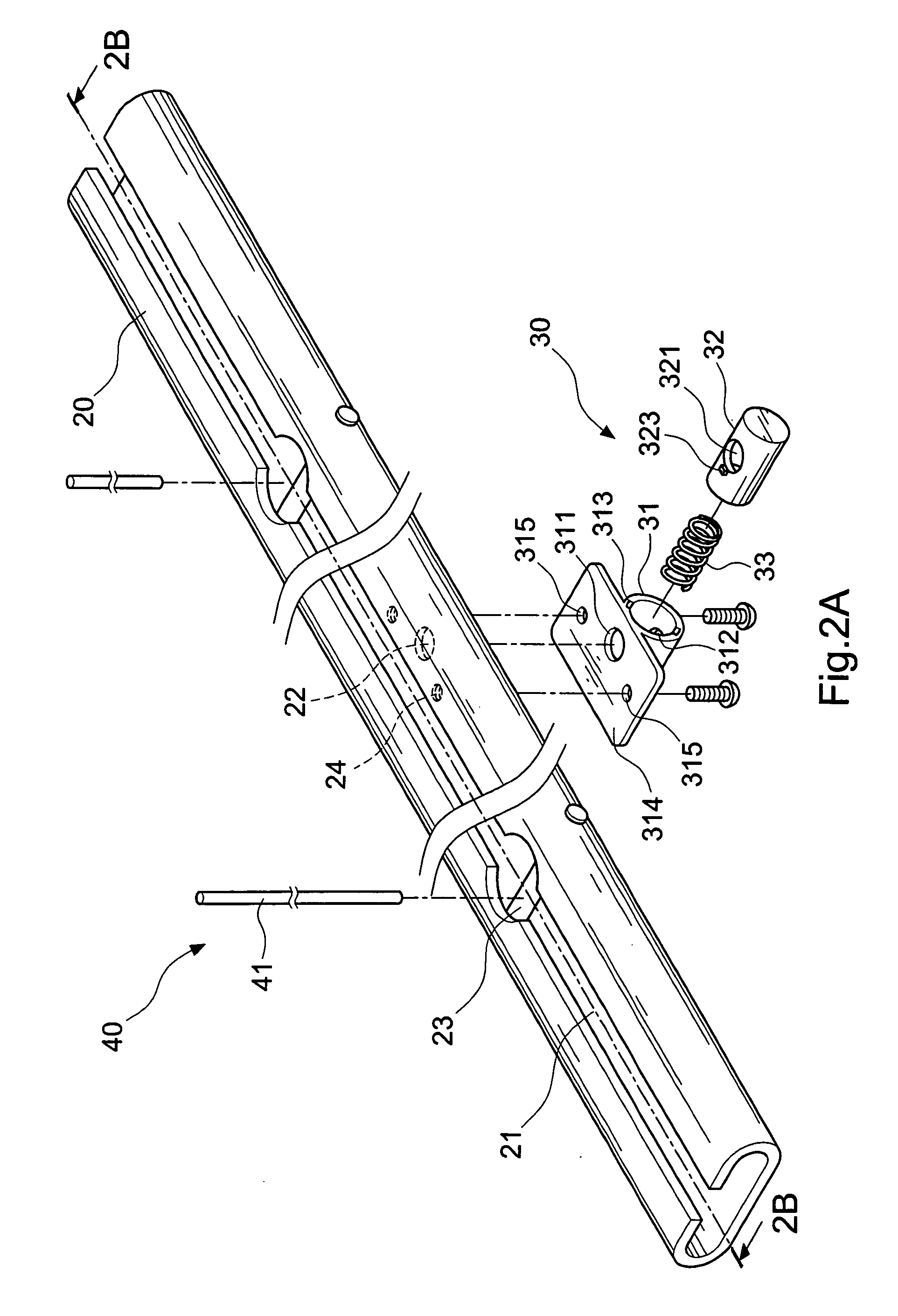
[0019] Please refer to FIG. 2A for an embodiment of the invention. The window shade lift cord apparatus according to the invention mainly includes a seat 20, a control switch 30 and a cord assembly 40.
[0020] The seat 20 is an elongate and hollow structure having a slot 21 on the top, an aperture 22 on the bottom leading to the interior and a plurality of axles 23 on two sides of the aperture 22 vertical to the axis of the long side of the seat 20. The number of the axles 23 mating the number of cords of the lift cord assembly 40. In this embodiment, there are two axles 23 located on two sides of the aperture 22.
[0021] The control switch 30 is fastened to the bottom side of the seat 20 corresponding to the aperture 22. It mainly includes an anchor member 31 and a depressing member 32 that are movably coupled together without separating, and an elastic element 33 located between the anchor member 31 and the depressing member 32. The elastic element 33 is resilient such as a spring t...
PUM
 Abstract
Description
Claims
Application Information