Thrombus removal and intravascular distal embolic protection device

a protection device and thrombosis technology, applied in the field of medical devices, systems and methods, can solve the problems of insufficient “warm” and blood clots or emboli to the pulmonary arteries of the lung, potentially life-threatening conditions, brain, etc., and achieve the effect of facilitating the retraction of tubular mesh and/or inner sheath, and facilitating the advancement of the clot extraction catheter

Active Publication Date: 2016-09-13
SOS THOMAS A
View PDF97 Cites 39 Cited by
  • Summary
  • Abstract
  • Description
  • Claims
  • Application Information

AI Technical Summary

Benefits of technology

[0009]Referring back to the other components of the clot extraction catheter, the proximal end of the tapered tip may have a rounded lip to reduce interference as the catheter is drawn proximally through a bodily lumen or cavity.
[0011]The control wires may be retracted proximally to capture a clot or thrombus once the self-expanding rim and expandable tubular mesh is advanced and positioned distally of the clot or thrombus. The expandable tubular mesh, once capturing the blood clot, may be closed by advancing the inner sheath over the control wires and at least a portion of the expandable tubular mesh. Alternatively or in combination, the inner sheath may be advanced over the control wires and at least a portion of the expandable tubular mesh. In some embodiments, the two chord control wires are advanced further than the main wire to change the angle of the rim to a more obtuse angle relative to the longitudinal axis of the inner sheath to facilitate advancement of the inner sheath over the control wires. The expandable tubular mesh and the captured clot or thrombus may be gradually molded to the inner diameter of the inner sheath and / or the outer sheath. While very chronic and organized thrombus may resist deformation and molding, such clots may crumble in the expandable tubular mesh when withdrawn into the inner sheath and / or the outer sheath.
[0016]The clot extraction catheter may further comprise an inner pusher tube advancable within the inner sheath. The inner pusher tube, when advanced, may be disposed within the lumen of the inner sheath and in-between the control wires. The pusher tube may comprise a guidewire lumen through which a guidewire can be passed through. The pusher tube may be used to facilitate advancement of the clot extraction catheter through a subject's vasculature to reach a clot. The pusher tube may facilitate advancement of the clot extraction catheter through tortuous vasculature. For example, the pusher tube may be used to advance the clot extraction catheter through a femoral artery, through the inferior vena cava (IVC), and through the right atrium and ventricle of the heart to reach a pulmonary artery. Alternatively or in combination, the clot extraction catheter may be advanced through this tortuous vasculature without the aid of the inner pusher tube. The clot extraction catheter and its component elements such as the inner sheath may be sufficiently flexible and compliant such that it may navigate through the tortuous vasculature while accommodating for the twists and turns of the vasculature and while minimizing the exertion of any damaging force to the vessel walls.
[0019]Aspects of the present disclosure may further provide a system for extracting a clot from a blood vessel. The system may comprise the clot extraction catheter as described herein. The system may further comprise a guidewire advancable within the inner sheath of the clot extraction catheter. The guidewire may comprise a bulb near a distal end of the guidewire and may also comprise a soft, floppy tip distal to the bulb. The bulb of the guidewire may be used to facilitate retraction of the tubular mesh and / or inner sheath. The distal end of the tapered tip distal of the tubular mesh may abut the bulb as the guidewire is retracted. Afterwards, further retraction of the guidewire may additionally retract the tubular mesh and / or inner sheath. The guidewire may be used to facilitate the advancement of the clot extraction catheter through a subject's vasculature to reach a clot. The guidewire may first be advanced through the vasculature to reach a target location before the clot extraction catheter is advanced over the guidewire. For example, the guidewire and / or clot extraction catheter may be introduced into the vasculature initially through a jugular or femoral vein before reaching the superior vena cava (SVC) or inferior vena cava (IVC), respectively.

Problems solved by technology

Typically, blood clot or emboli to the pulmonary arteries of the lung, the brain, the peripheral arteries of the extremities, in the venous system, or in dialysis access vessels are potentially life and / or limb threatening conditions.
Thrombolytic drugs typically require several hours to days to accomplish dissolving these clots.
Frequently, there is not sufficient “warm” ischemic time for the target organ to permit such a long time to reperfusion.
Thrombolytic drugs also have an approximately 5% incidence of major complications such as hemorrhage and stroke.
Currently available mechanical devices may not be effective in the presence of large volumes of thrombus or may have a very large diameter and may be stiff.
Thus, these devices may be difficult or impossible to advance into curved and tortuous vessels such as the pulmonary arteries.
The “Hydrolyzer” devices available in the marketplace may break up a clot and suction the resulting particles out, but may infuse large volumes of fluid as part of their action.
Such infusion may be physiologically difficult to handle for the patient.
Most of these devices may also hemolyze blood, which may result in damage to the kidneys and may also cause distal emboli.

Method used


Image

  • Thrombus removal and intravascular distal embolic protection device
  • Thrombus removal and intravascular distal embolic protection device
  • Thrombus removal and intravascular distal embolic protection device

Examples


Embodiment Construction

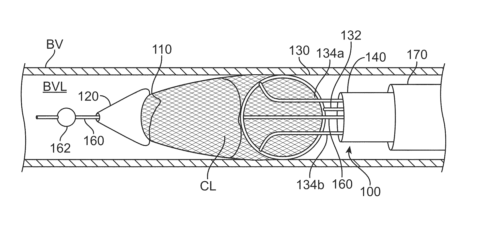
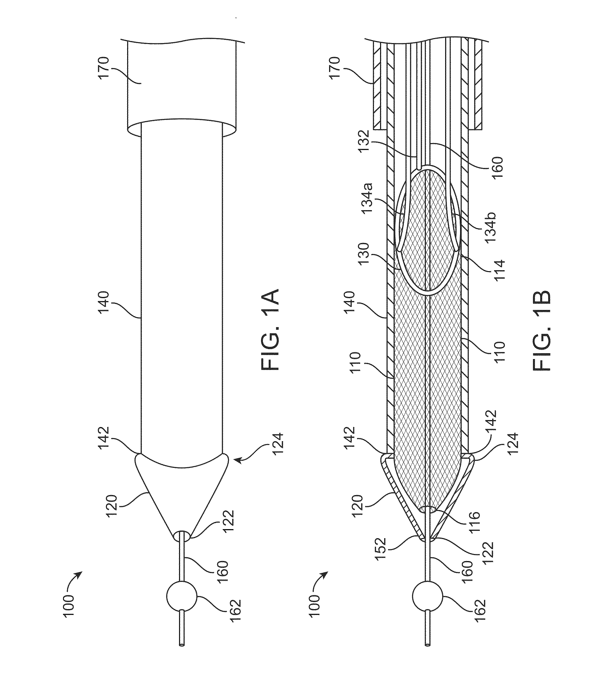
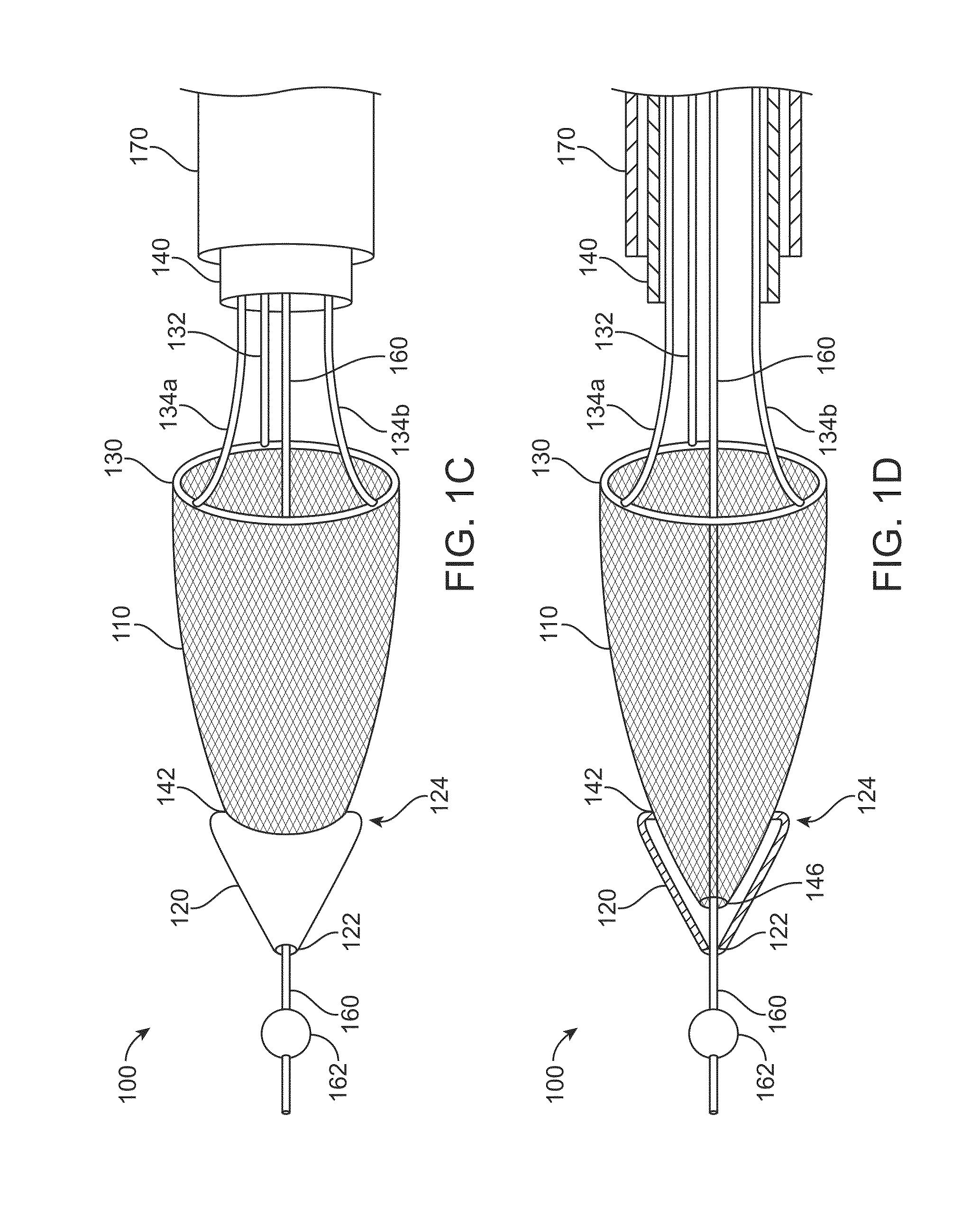
[0054]FIGS. 1A to 1D show a clot extraction catheter 100 according to many embodiments. FIGS. 1A and 1B show the clot extraction catheter 100 with its tubular mesh or clot capture basket 110 in a constrained, delivery configuration. The tubular mesh or clot capture basket 110 may be self-expanding and may comprise a shape-memory material or metal such as Nitinol (NiTi). The clot extraction catheter 100 comprises a tubular inner sheath 140 which is advancable over the tubular mesh 110 to constrain the tubular mesh 110. The tubular inner sheath 140 can be retracted proximally to release the tubular mesh 110 as shown in FIGS. 1C and 1D. When unconstrained, the tubular mesh 110 may resiliently assume its unconstrained configuration which may be in the form of a tube sock-like structure. Alternatively or in combination, the tubular mesh 110 may comprise a heat-based shape memory material so that the unconstrained tubular mesh 110 may assume the tube sock-like structure when exposed to bo...


PUM


Abstract

A clot extraction catheter comprises a tubular mesh, a tapered tip fixed to the tubular mesh distal end, a rim attached to the tubular mesh proximal end, control wires, a guidewire channel, an inner sheath, and an outer sheath advancable over the guidewire channel and inner sheath. To extract a clot, the catheter is advanced through the clot over a guidewire. The inner sheath is retracted relative to the control wires and the tubular mesh, allowing the rim and the tubular mesh to expand. The tubular mesh is retracted to capture the clot, constrained proximally by the distal portion of the inner sheath, and retracted with the inner sheath into the outer sheath. The control wires may be manipulated to control the angle of the rim relative to the longitudinal axis of the sheaths, facilitating clot capture and retraction of the tubular mesh into the sheaths thereafter.

Description

CROSS-REFERENCE[0001]This application is a continuation-in-part of U.S. patent application Ser. No. 14 / 289,027, filed May 28, 2014, which claims the benefit of U.S. Provisional Application No. 61 / 828,264, filed May 29, 2013, the full disclosures of which are incorporated herein by reference.BACKGROUND[0002]The present disclosure generally relates to medical devices, systems, and methods. In particular, the present disclosure generally relates to the removal of intravascular or intracavitary thrombus or other material which may frequently require removal to restore blood flow or other normal functionality of the organ system affected.[0003]Typically, blood clot or emboli to the pulmonary arteries of the lung, the brain, the peripheral arteries of the extremities, in the venous system, or in dialysis access vessels are potentially life and / or limb threatening conditions. These clots are typically cleared when medically indicated by either pharmacological (thrombolytic and / or anticoagu...

Claims


Application Information

Patent Timeline
Patent Type & Authority Patents(United States)
IPC IPC(8): A61B17/221A61B17/3207A61B17/22
CPCA61B17/221A61B17/22032A61B17/3207A61B17/320758A61B2017/2212A61B2017/2215A61B2017/22042A61B2017/22049A61B2017/22065A61B2017/22094A61B2017/320733A61B2017/320775
Inventor SOS, THOMAS A.
Owner SOS THOMAS A
Why Eureka
Try Eureka