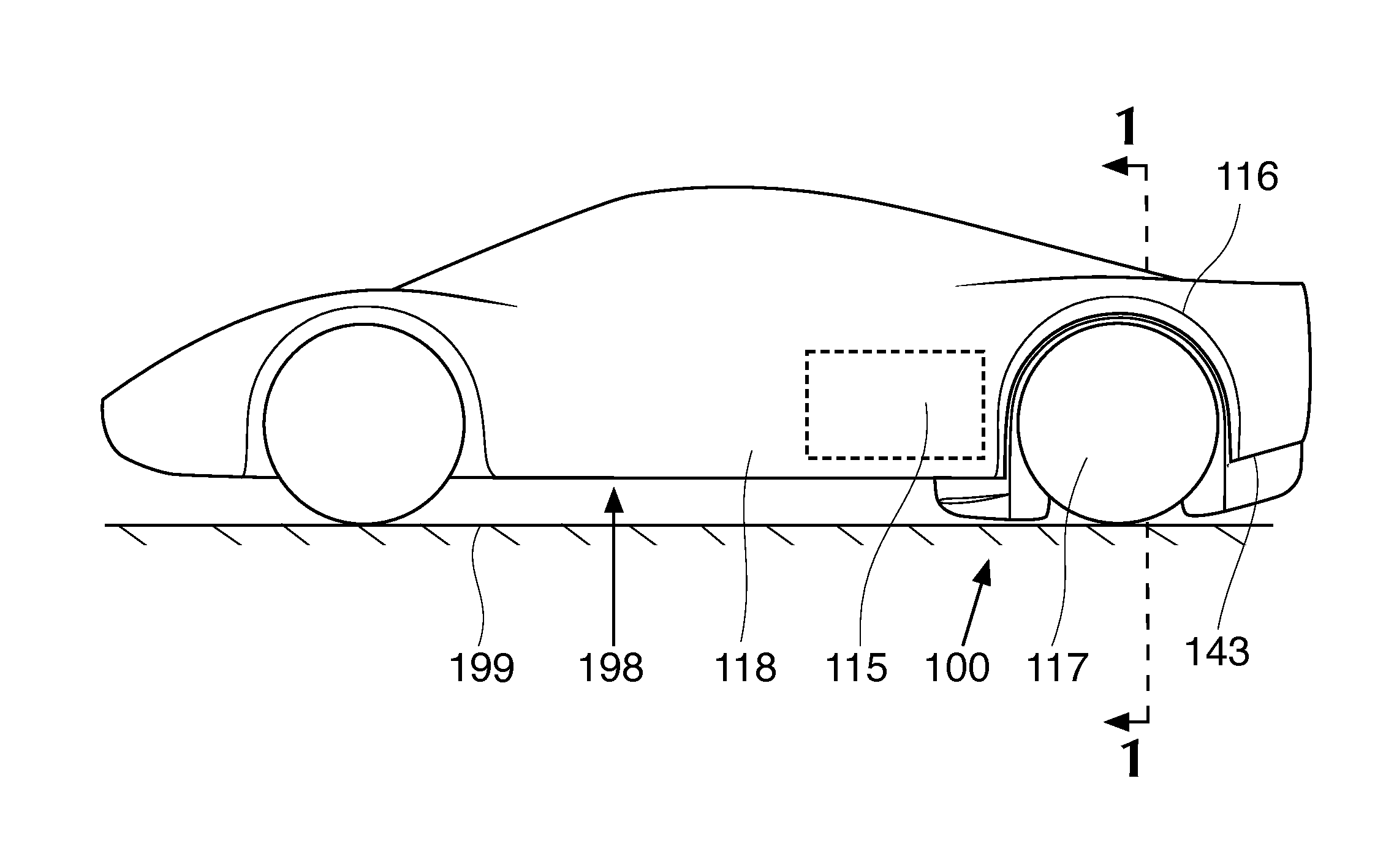
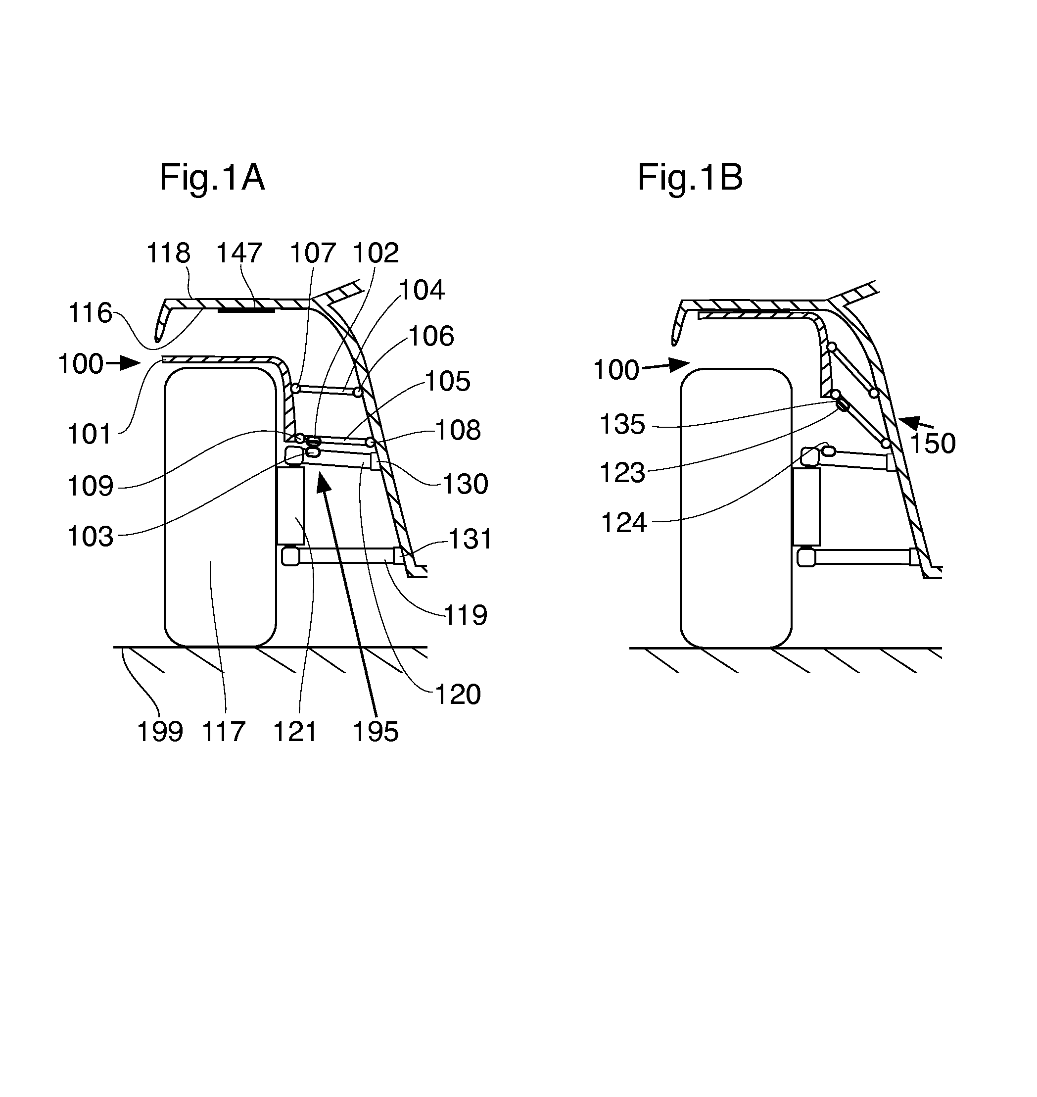
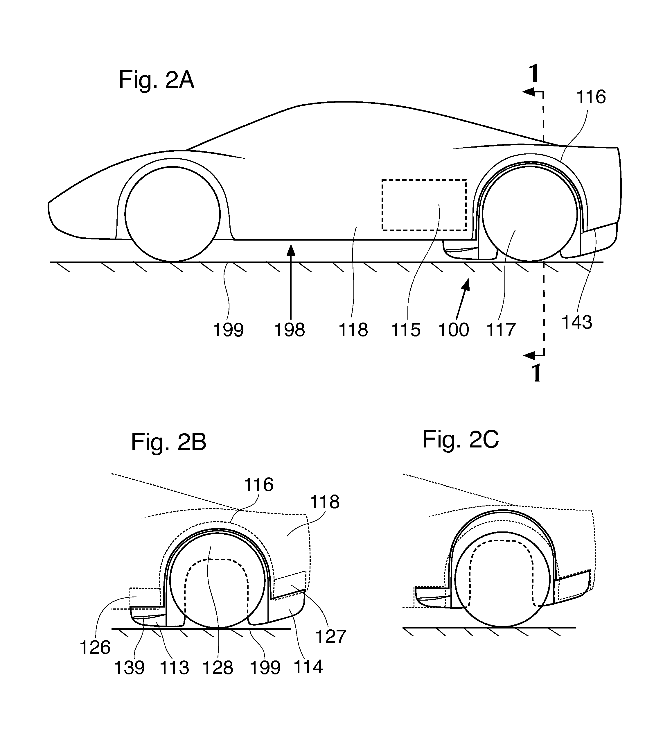
Retractable wheel fairings for motor vehicles
a technology of motor vehicles and fairings, which is applied in the direction of roofs, instruments, process and machine control, etc., can solve the problems of increasing downforce, reducing aerodynamic drag, and increasing the mass of the wheel fairing device not fixedly attached to the suspension of the vehicle, so as to reduce the build-up of high-pressure air, reduce the aerodynamic drag, and smooth the air flow
- Summary
- Abstract
- Description
- Claims
- Application Information
AI Technical Summary
Benefits of technology
Problems solved by technology
Method used
Image
Examples
first additional embodiment
FIGS. 3B, 5A, 5B
[0202]FIG. 3B is a plan view of a first additional embodiment of a wheel fairing device 200 in accordance with the present invention. FIG. 5A is a left side elevation view of the first additional embodiment in accordance with the present invention with a fairing body 201 in deployed position. FIG. 5B is the corresponding view of the same embodiment with the fairing body 201 in retracted position.
[0203]This first additional embodiment is structurally and operationally the same as the basic embodiment described above, with some exceptions. These exceptions are that the fairing body 201 consists largely of a leading element 213 before the vehicle wheel 117. The fairing body 201 of this first additional embodiment does not include a trailing element, and the wheel pant 228 is represented by a short length of skirt continuous with the medial rear edge of the leading element 213.
[0204]The leading element 213 bears a dive plane 239 and is accommodated by a leading element d...
second additional embodiment
FIGS. 6A, 6B, 6C, 6D
[0208]FIG. 6A is a left side elevation view of a second additional embodiment of a wheel fairing device 300 in accordance with the present invention with a fairing body 301 in deployed position. FIG. 6B is the corresponding view, with the fairing body 301 in the retracted position. FIG. 6C is a rear cross-sectional view of the second additional embodiment in deployed position. FIG. 6D is a perspective rear three-quarter view of a front pantographic guide linkage 304 that is used in this embodiment.
[0209]This second additional embodiment is structurally and operationally the same as the basic embodiment described above, with some exceptions. These exceptions are that the fairing body guide 350 consists of a pair of pantographic guide linkages, a front pantographic guide linkage 304 located above the leading element 313 and a rear pantographic guide linkage 305 located on the wheel pant 328. Additionally, the upper support bracket 302 is mounted directly to the fai...
third additional embodiment
FIGS. 7A, 7B
[0215]FIGS. 7A and 7B are left side elevation views of a third additional embodiment of a wheel fairing device 400 in accordance with the present invention with the fairing body 401 in deployed (FIG. 7A) and retracted (FIG. 7B) positions. This third additional embodiment is structurally and operationally the same as the first additional embodiment of the present invention described above, with a few exceptions. These exceptions are that the simple fairing body 401, when deployed, is supported from the suspension by a support linkage 440 that depends from the upper control arm 120 of the suspension, rather than pressing upon the suspension as in the basic embodiment and the other additional embodiments described herein. It therefore lacks an upper support bracket 102 and a lower support bracket 103.
[0216]The support linkage 440 consists of a length of Kevlar webbing secured at its upper end to the upper control arm 120 through the support linkage upper mounting bracket 44...
PUM
 Abstract
Description
Claims
Application Information
 - R&D
- Intellectual Property
- Life Sciences
- Materials
- Tech Scout
- Unparalleled Data Quality
- Higher Quality Content
- 60% Fewer Hallucinations
Browse by: Latest US Patents, China's latest patents, Technical Efficacy Thesaurus, Application Domain, Technology Topic, Popular Technical Reports.
© 2025 PatSnap. All rights reserved.Legal|Privacy policy|Modern Slavery Act Transparency Statement|Sitemap|About US| Contact US: help@patsnap.com


