Media transport system

Active Publication Date: 2006-10-26
XEROX CORP
View PDF62 Cites 3 Cited by
  • Summary
  • Abstract
  • Description
  • Claims
  • Application Information

AI Technical Summary

Benefits of technology

[0046] A method of processing documents for transport through a printing system is provided for enhancing document control and reducing transport path distance. The printing system includes an inverter assembly comprising nip drive rollers for grasping the document and a marking engine. The method includes transporting at least two documents to the inverter assembly. The at least two documents are then transported from the inverter assembly in a first egress order through a marking engine for marking on each of a first side. The documents are returned along a duplex path to the inverter assembly. After returning, the at least two documents can be transported from the inverter assembly in a second egress order through the marking engine for marking on each of a second side.
[0047] A method of processing documen

Problems solved by technology

Inverters are thus fairly simple in their functional result; however, complexities occur as the printing system is required to handle different sizes and types of documents and where the marking engines themselves are arranged in a parallel printing system to effect different types of printing, e.g., black only printing versus color or custom color printing.
This requires a relatively long and expensive upstream paper handling path.
As these systems may be disposed along the main process path, the machine size and paper path reliab

Method used


Image

  • Media transport system
  • Media transport system
  • Media transport system

Examples


first embodiment

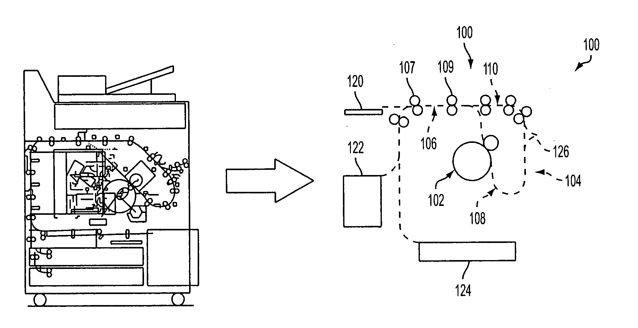
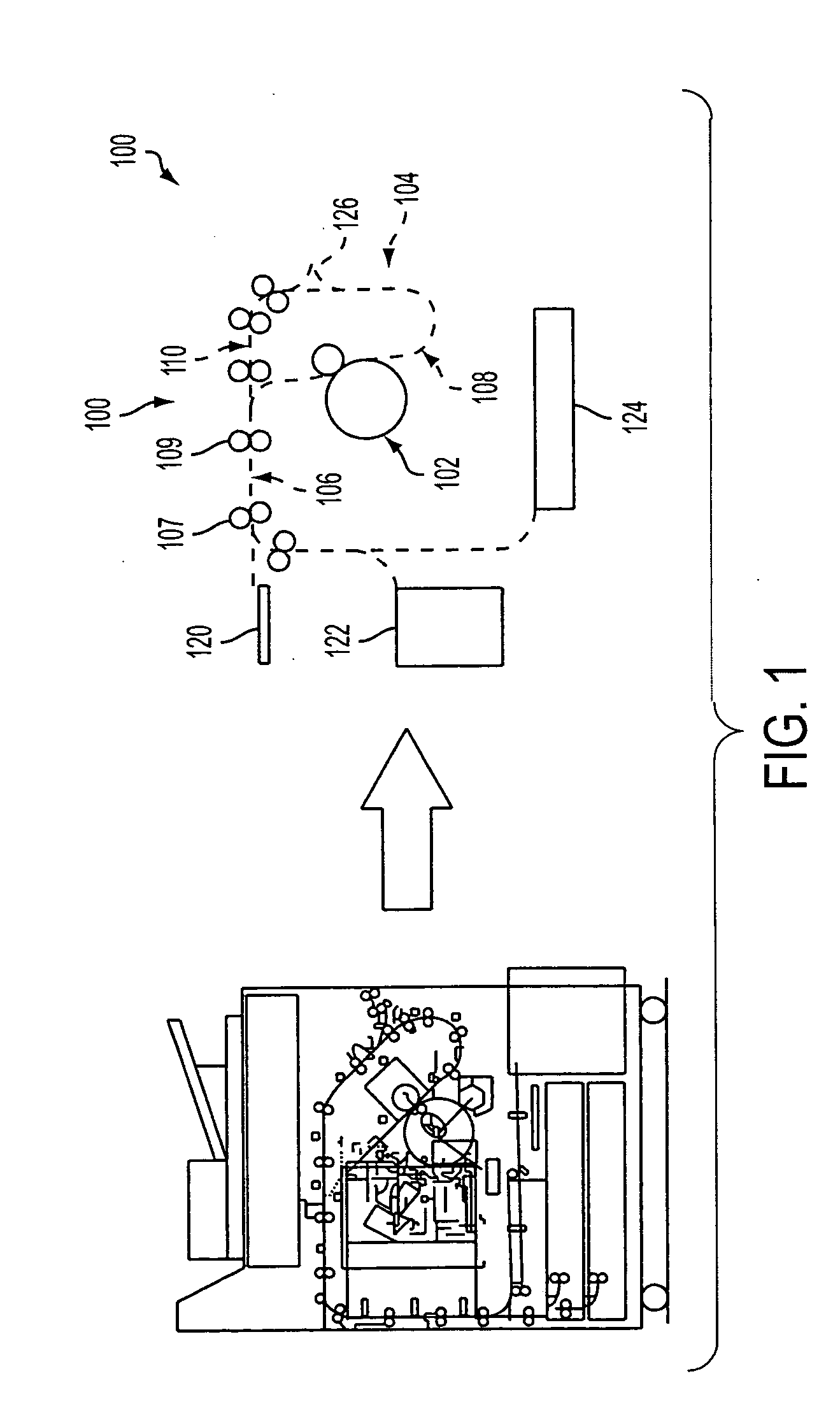
[0061] Referring now to FIGS. 1-3, a schematic view is therein shown of a sheet printing system (i.e. solid ink printer) or xerographic device 100 comprising a marking engine according to a More particularly, printing system 100 is illustrated as including primary elements comprising a marking engine or IOT 102 and a reversing roll or inverter media transport system 104. The transport system 104 further includes an entrance path 106, a marking path 108, and a duplex path 110 for moving media sheets or documents through the printing system 100. The entrance path 106 can include more than one reversing drive nip system. As shown in FIG. 1, the entrance path can include two reversing drive nip systems 107, 109.

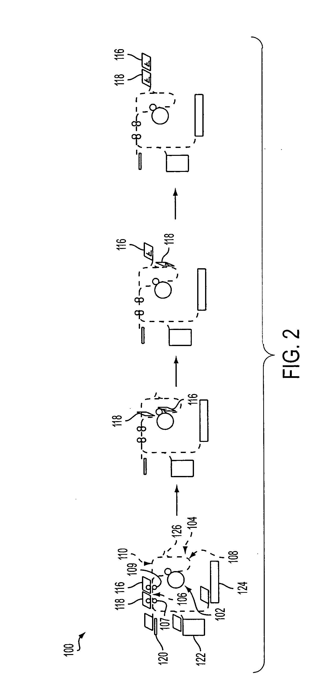
[0062] Referring now to FIG. 2, the printing system 100 can move selective media sheets 116, 118 from feeder sources 120, 122, 124 onto the entrance path 106, through the IOT 102 on marking path 108, and outward on an exit path 126. In this manner, media sheets can move in tande...

second embodiment

[0064] Referring now to FIGS. 4-6, a schematic view is therein shown of a printing system or xerographic device 200 comprising a marking engine according to a More particularly, printing system 200 is illustrated as including primary elements comprising a marking engine or IOT 202 and a reversing roll or inverter media transport system 204. The transport system 204 further includes an entrance path 206, a marking path 208, and a duplex path 210 for moving media sheets or documents through the printing system 200. The entrance path 206 can include more than one reversing drive nip system. As shown in FIG. 4 the entrance path includes three reversing drive nip systems 207, 209, 211.

[0065] Referring now to FIG. 5, the printing system 200 can move selective media sheets 216, 218 from feeder sources 220, 222 onto the entrance path 206, through the IOT 202 on marking path 208. It is to be appreciated that the IOT 202 is a face down marking process. The sheets 216, 218 can be inverted bef...

third embodiment

[0067] Referring now to FIGS. 7-9, a schematic view is therein shown of a printing system or xerographic device 300 comprising a marking engine according to a More particularly, printing system 300 is illustrated as including primary elements comprising a marking engine or IOT 302 and a reversing roll or inverter media transport system 304. The transport system 304 further includes an entrance path 306, a marking path 308, and a duplex path 310 for moving media sheets or documents through the printing system 300. The entrance path 306 can include more than one reversing drive nip system. As shown in FIG. 8, the entrance path 306 includes three reversing drive nip systems 307, 309, 311.

[0068] Referring now to FIG. 8, the printing system 300 can move selective media sheets 316, 318 from feeder sources 322, 324 up into the entrance path 306 and inverted before moving through the IOT 302 on marking path 308. It is to be appreciated that the IOT 302 is a face down marking process. The s...


PUM


Abstract

A printing system is provided comprising a marking engine and an inverter. The inverter includes an entrance path having a first reversing inverter drive nip system and a second reversing drive nip system. The printing system further includes a marking path and a duplex path whereby a plurality of media sheets move through the entrance path, the marking path and the duplex path in a first order sequence. The plurality of media sheets return to the entrance path wherein the plurality of media sheets are inverted and moved again through the marking path in a second order sequence.

Description

CROSS REFERENCE TO RELATED PATENTS AND APPLICATIONS [0001] The following applications, the disclosures of each being totally incorporated herein by reference are mentioned: [0002] U.S. Provisional Application Ser. No. 60 / 631,651 (Attorney Docket No. 20031830-US-PSP), filed Nov. 30, 2004, entitled “TIGHTLY INTEGRATED PARALLEL PRINTING ARCHITECTURE MAKING USE OF COMBINED COLOR AND MONOCHROME ENGINES,” by David G. Anderson, et al.; [0003] U.S. Provisional Patent Application Ser. No. 60 / 631,918 (Attorney Docket No. 20031867-US-PSP), filed Nov. 30, 2004, entitled “PRINTING SYSTEM WITH MULTIPLE OPERATIONS FOR FINAL APPEARANCE AND PERMANENCE,” by David G. Anderson et al.; [0004] U.S. Provisional Patent Application Ser. No. 60 / 631,921 (Attorney Docket No. 20031867Q-US-PSP), filed Nov. 30, 2004, entitled “PRINTING SYSTEM WITH MULTIPLE OPERATIONS FOR FINAL APPEARANCE AND PERMANENCE,” by David G. Anderson et al.; [0005] U.S. application Ser. No. 10 / 761,522 (Attorney Docket A2423-US-NP), filed ...

Claims


Application Information

Patent Timeline
IPC IPC(8): B65H29/00
CPCB41J3/60G03G15/232B41J13/0045B41J11/42B41J17/14
Inventor MANDEL, BARRY PAULLEO, MICHAEL F.CHOI, INJAE
Owner XEROX CORP
Why Eureka
Try Eureka