Zoned thermal monitoring

Active Publication Date: 2006-10-26
ADVANCED MICRO DEVICES INC
View PDF6 Cites 43 Cited by
  • Summary
  • Abstract
  • Description
  • Claims
  • Application Information

AI Technical Summary

Benefits of technology

[0006] Thus, it is desirable to be able to detect when certain zones of the integrated circuit die are much hotter than others in order to help ensure that the integrated device remain below a certain maximum temperature. Accordingly, in one embodiment an integrated circuit includes a first temperature sensing device and a first oscillator circuit positioned adjacent to the first temperature sensing device and at least one additional oscillator circuit. A temperature of a region of the integrated circuit associated with the additional oscillator circuit is determined as a function of an oscillation frequency of the additional oscillator circuit and an oscillation frequency of the first oscillator circuit. In an embodiment, a temperature determined by the first temperature sensing device is utilized in determining the temperature of the region associated with the additional oscillator circuit. The integrated circuit may further include a storage location storing one or more calibration factors utilized in determining the temperature of the region associated with the additional oscillator circuit. One of the calibration factors may be used to account for a location of the additional oscillator circuit with respect to a local high temperature region of the integrated circuit. One of the calibration factors may be used to calibrate the temperature reported by the first temperature sensing device. One of the calibration factors may be used for calibrating the additional oscillator according to power utilization of the integrated circuit. In an embodiment, the integrated circuit includes a counter circuit coupled to determine a count value corresponding to the oscillation frequency of the additional oscillator circuit. The count value may be determined by counting a number of cycles of a reference clock occurring in a predetermined number of additional oscillator cycles. The temperature of the region of the integrated circuit associated with the additional oscillator circuit is determined independently of a frequency of the reference clock.
[0007] In another embodiment a method is provide that includes determining respective temperatures at a plurality of locations in an integrated circuit as a function of respective oscillation frequencies of a plurality of temperature sensitive oscillator circuits on the integrated circuit, an oscillation frequency of a correlation oscillator circuit on the integrated circuit, and

Problems solved by technology

If the temperature of an integrated circuit, or a portion of an integrat

Method used


Image

  • Zoned thermal monitoring
  • Zoned thermal monitoring
  • Zoned thermal monitoring

Examples


Embodiment Construction

)

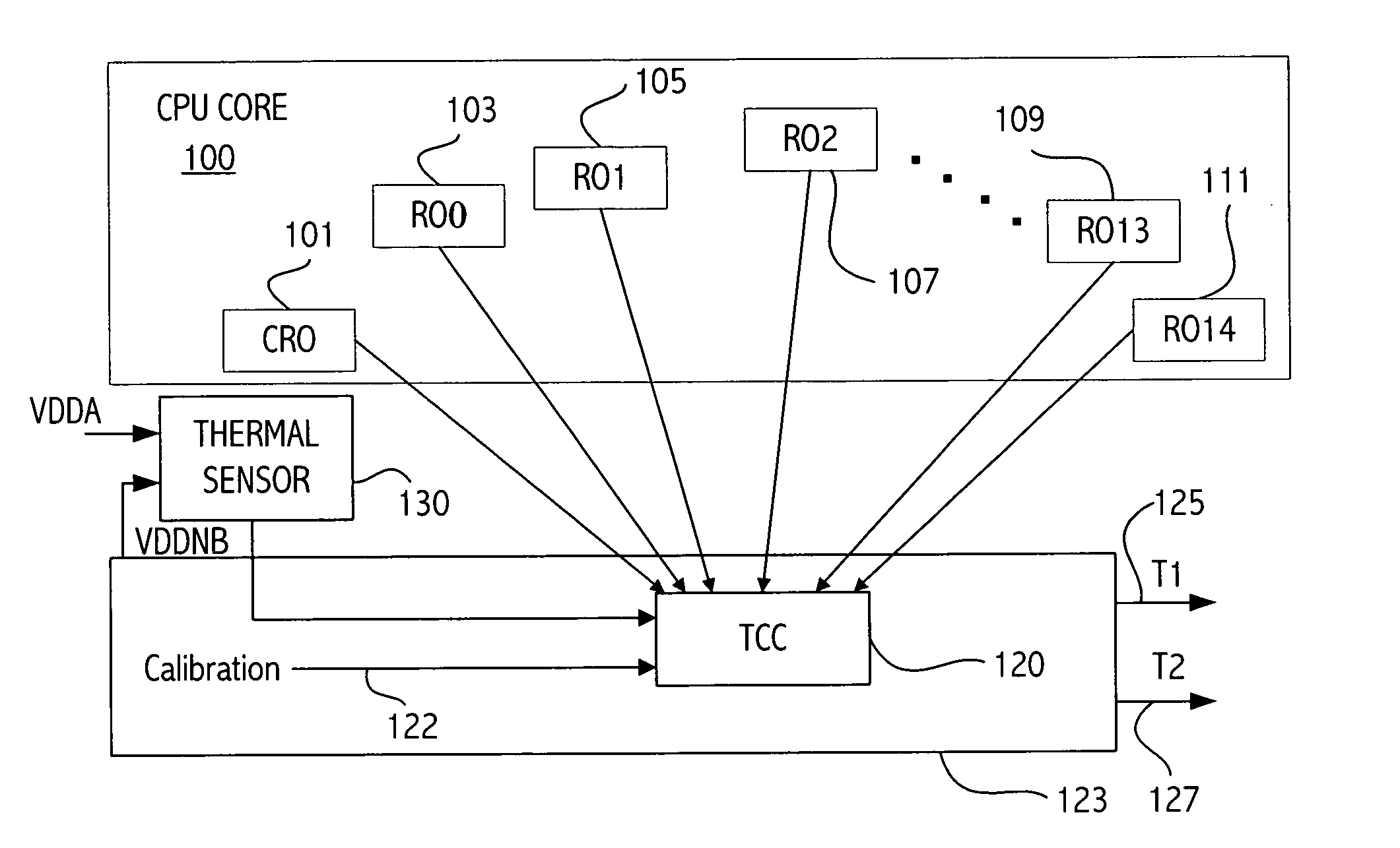
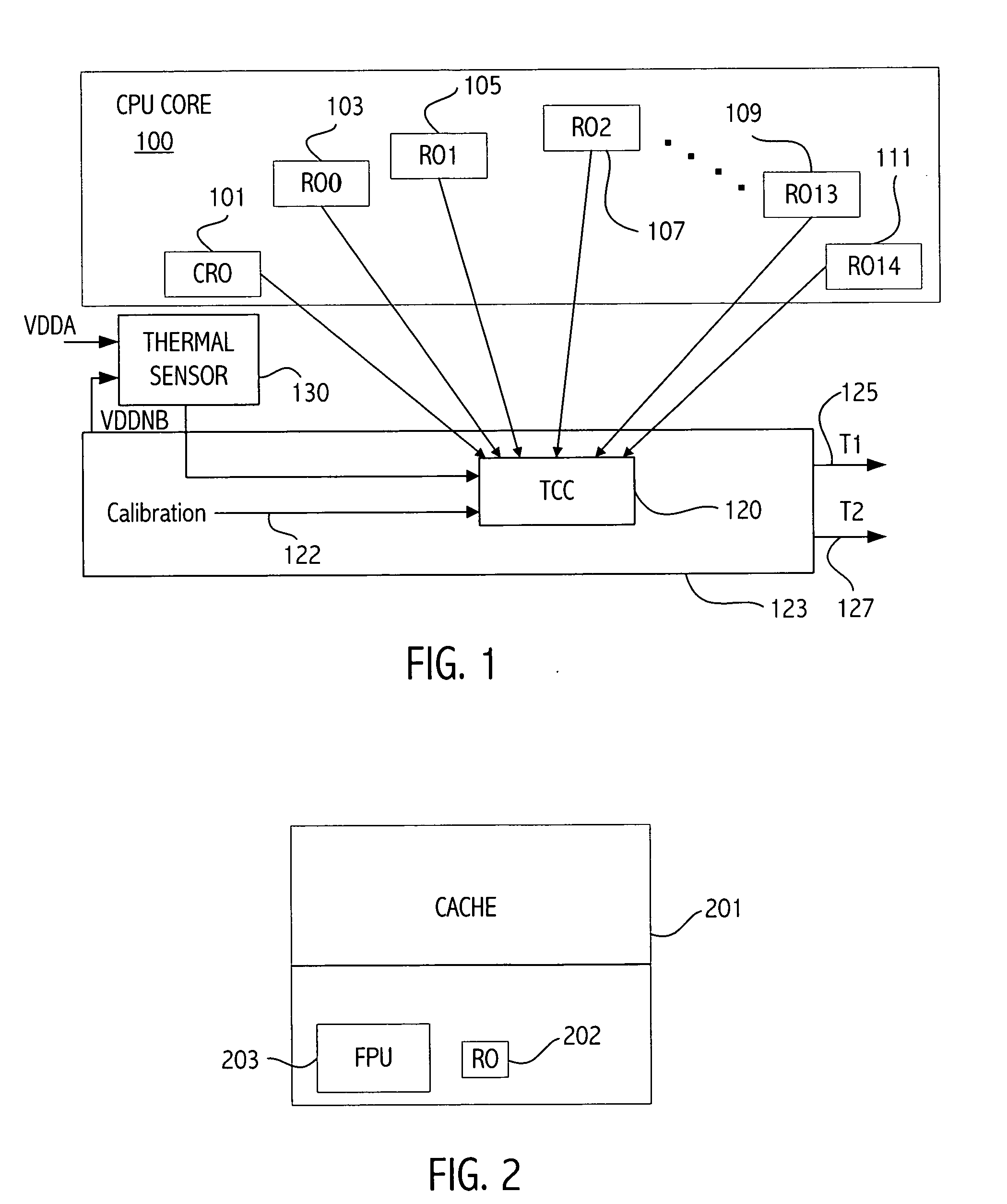
[0018] Referring to FIG. 1, illustrated is an exemplary thermal architecture for a microprocessor according to an embodiment of the invention. The microprocessor includes the CPU core 100. The CPU core 100 includes a plurality of ring oscillators whose oscillation frequency is used to determine temperatures of regions of the CPU core adjacent to the ring oscillators. The thermal architecture includes a correlation ring oscillator (CRO) 101 and ring oscillators (RO) 103-111. In the illustrated embodiment there are 15 ring oscillators (RO0-RO14) in addition to the correlation ring oscillator CRO 101. Other embodiments may have more or less ring oscillators. The ring oscillators RO0-R014 are disposed in various locations in the CPU core in order to measure the temperature at a variety of locations in the integrated circuit. Large thermal gradients may be present on the die. For example, regions of the die may differ by, e.g., 50° C. Thermal energy spreads relatively slowly and therefo...


PUM


Abstract

An integrated circuit includes a first temperature sensing device providing an indication of a sensed temperature, a correlation oscillator circuit positioned adjacent to the first temperature sensing device, a plurality of other oscillator circuits, and storage locations storing calibration factors associated with at least the first temperature sensing device and the plurality of other oscillator circuits. A temperature calculation circuit determines temperatures of various locations in the integrated circuit. Each of the temperatures is determined according to an oscillation frequency of a respective one of the other oscillators, the oscillation frequency of the correlation ring oscillator, the temperature of the first temperature sensing device, and one or more stored calibration factors.

Description

BACKGROUND [0001] 1. Field of the Invention [0002] This invention relates to integrated circuit circuits and more particularly to thermal monitoring of integrated circuits. [0003] 2. Description of the Related Art [0004] Integrated circuits have typically measured temperature at a single point on an integrated circuit die, often using an analog (diode) structure. That one measured temperature was considered to be representative of the entire die area. However, in integrated circuits such as microprocessors the geometries utilized in the integrated circuit have decreased, speed has increased and power utilization has increased. The area around regions that are densely populated with switching transistors tend to be much hotter than the average die temperature resulting in a thermal gradient across the die. In fact areas of the die can be 25° C. hotter than other areas of the die in 130 nm technology at 90 W. The thermal gradient will be even greater as geometries continue to decrease...

Claims


Application Information

Patent Timeline
IPC IPC(8): H03L1/00
CPCG01K7/42G01K7/425G01K15/00H01L23/34H01L2924/0002H01L2924/00
Inventor BIENEK, MICHAEL D.HEWITT, LARRYLIU, HUINING
Owner ADVANCED MICRO DEVICES INC
Why Eureka
Try Eureka