Eureka AIR delivers breakthrough ideas for toughest innovation challenges, trusted by R&D personnel around the world.

User input device for electronic device

a user input and electronic device technology, applied in the field of electronic devices, can solve the problems of increasing the risk of repetitive strain injury to the user, other prior art user input devices are generally unsatisfactory, and occupy a relatively large amount of space or volume within the electronic devi

Inactive Publication Date: 2006-10-26
NOKIA CORP
View PDF27 Cites 194 Cited by
  • Summary
  • Abstract
  • Description
  • Claims
  • Application Information

AI Technical Summary

Benefits of technology

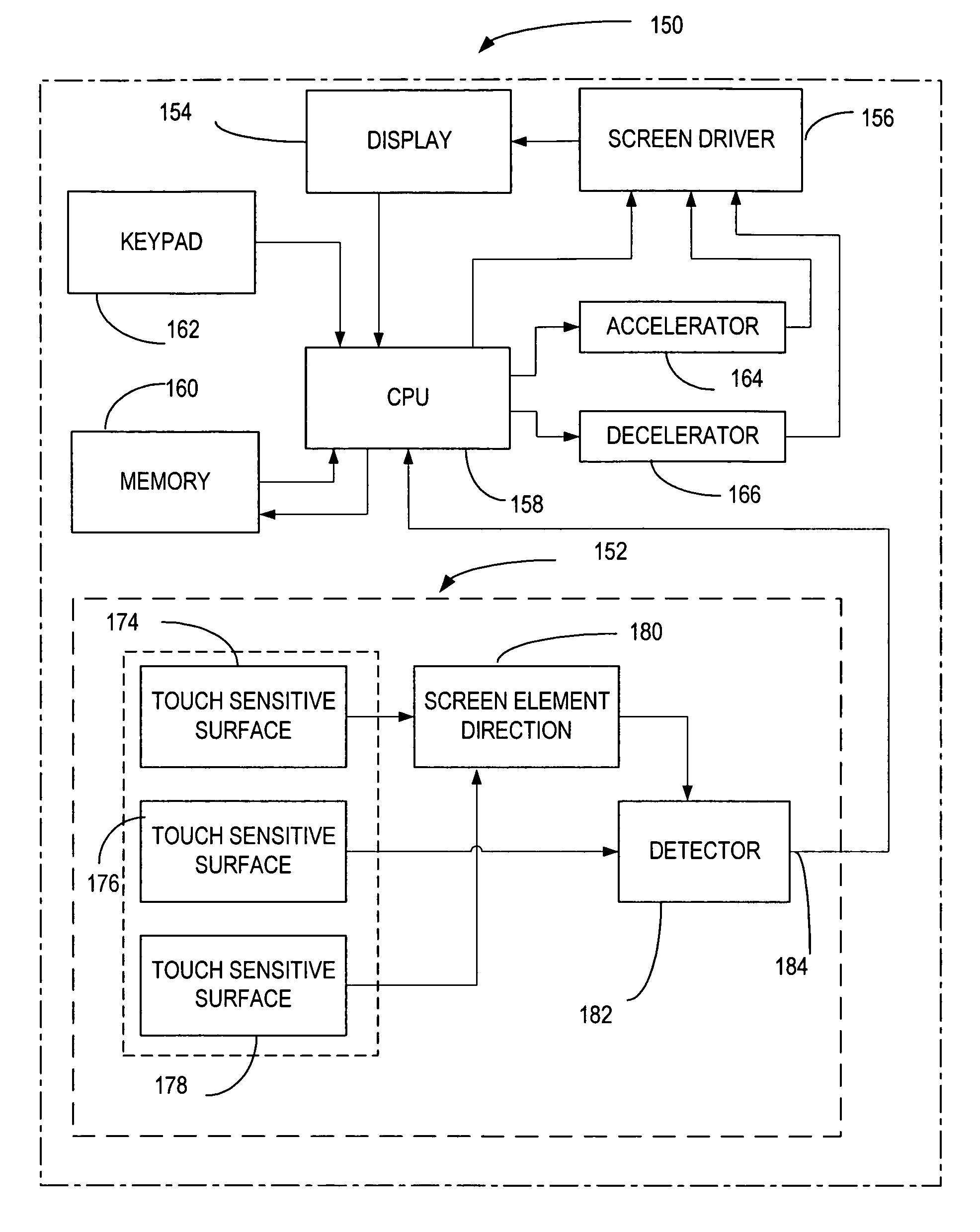
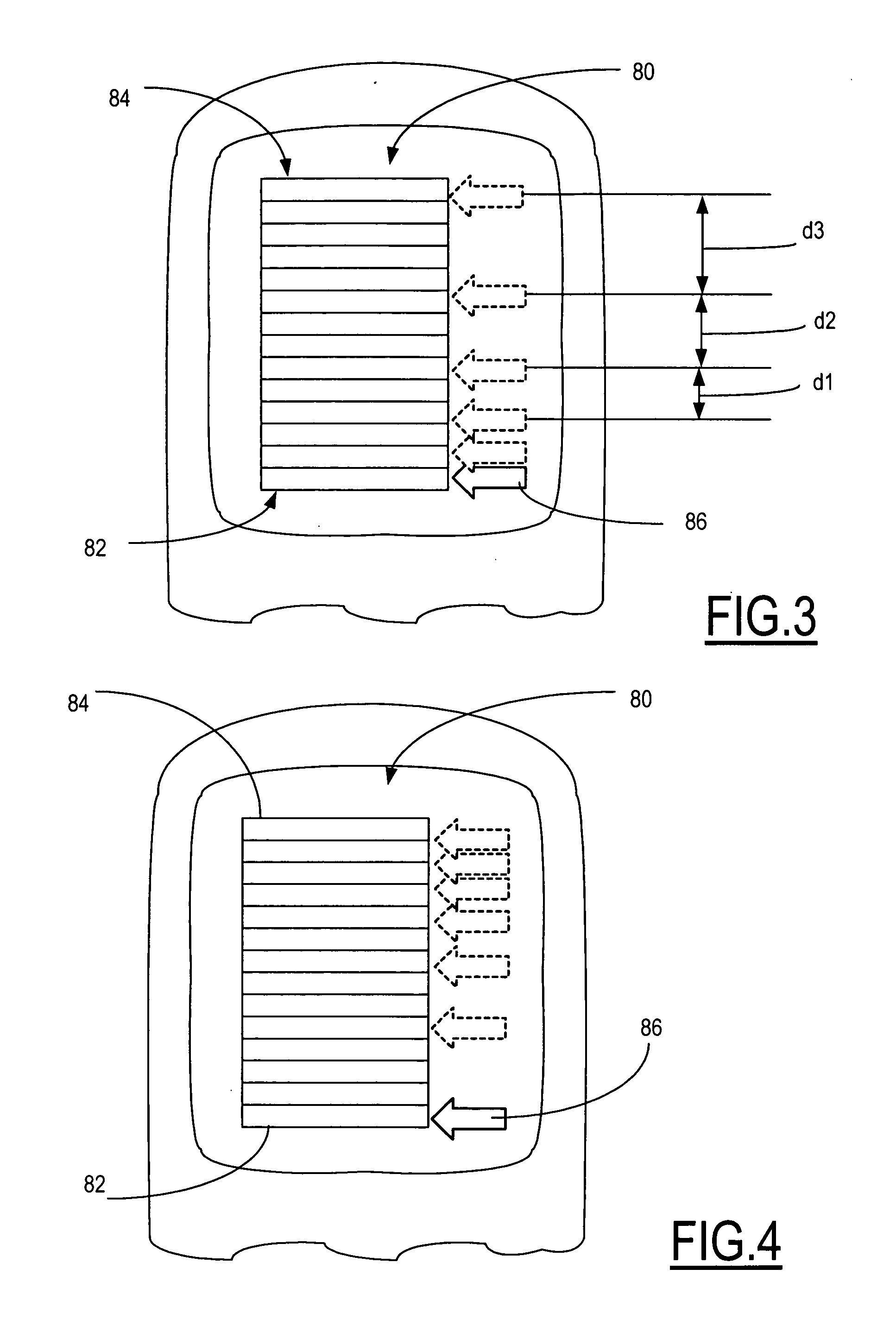
[0008] In accordance with a first aspect of the invention, an electronic device including a user input device is presented. The user input device includes a touch sensitive surface arranged to provide a pre-defined desired number of touch sensitive surface areas wherein each of the touch sensitive areas are associated with a corresponding pre-defined functionality. Appropriate control circuitry is responsive to touching contact with the touch sensitive surface for controlling the movement of a cursor in a display graphic such as a graphical user interface (GUI) shown on a screen carried by the electronic device. In a first pre-defined functionality a touching contact with a first pre-defined surface area causes the cursor to move in a corresponding first direction. In a second pre-defined functionality a touching contact with a second pre-defined surface area causes the cursor to move in a corresponding second direction, and in a third pre-defined functionality a touching contact with a third pre-defined surface area causes the cursor to stop movement. The first, second and third pre-defined surface areas are further arranged such th

Problems solved by technology

Other prior art user input devices are generally unsatisfactory due to inaccurate targeting and / or sequencing movement through the menu list using confusing interactions.
A further disadvantage is the prior art user input devices generally occupy a relatively large amount of space or volume within the electronic device or change the affect that the user input device has on the display depending upon the area over which the on-screen element is manipulated.
However, these user input devices typically require frequent and awkward movement with the operation of one or more keys to manipulate the on-screen element in the graphical user interface and which movements increase the risk of repetitive strain injury to the user.

Method used


Image

  • User input device for electronic device
  • User input device for electronic device
  • User input device for electronic device

Examples


Embodiment Construction

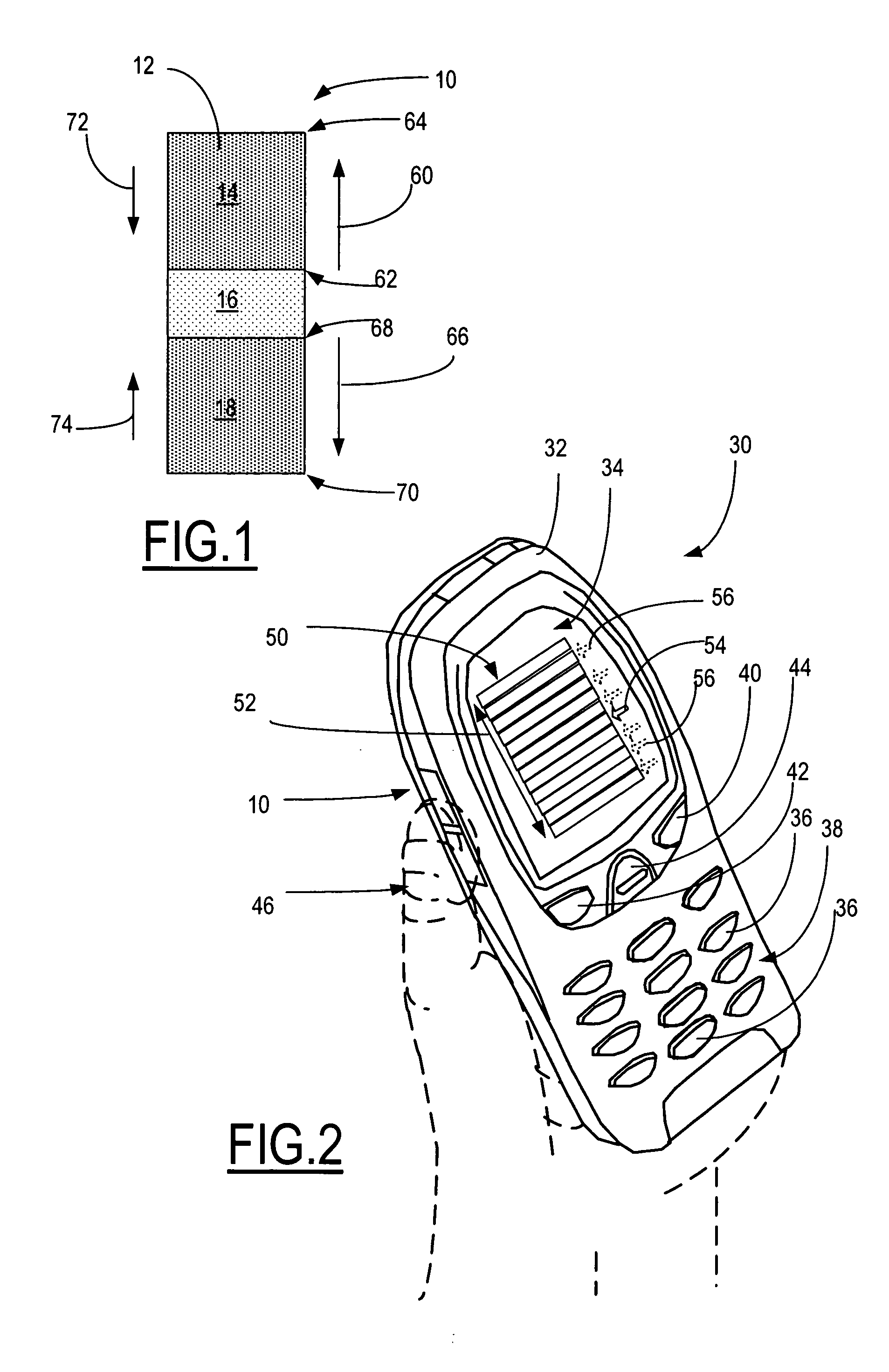
[0024] Turning now to the drawings and considering the invention in further detail, a first embodiment of a touch sensitive element arranged as a touch sensitive user input device is illustrated schematically in FIG. 1 and generally designated 10. The user input device 10 includes a major face surface 12. The surface 12 is a touch sensitive surface and is arranged to provide a desired number of pre-defined touch sensitive surface areas 14, 16, 18 wherein each of the touch sensitive surface areas 14, 16, 18 is associated with a corresponding pre-defined functionality. The touch sensitive surface 12 is of an appropriate material and construction arranged to carry out the intended functions and may be of any well known and understood technology for example, resistive, capacitive, inductive, electro-dielectric mechanical film (EMF), optical array such as a CCD or LED, or other suitable components arranged to map the surface area and respond to a touching contact thereon or in proximity ...


PUM


Abstract

A user input device for controlling the movement of a cursor in a graphical user interface (GUI) includes a touch sensitive surface arranged to provide a pre-defined number of touch sensitive surface areas substantially continuous with one another each of which is associated with a corresponding pre-defined functionality. Touching contact with the given surface area causes the cursor to move in the corresponding direction or to stop. The speed of the cursor is controlled by the touching contact which may be a sliding, tapping, pressure or other suitable contact.

Description

TECHNICAL FIELD [0001] The present invention relates generally to electronic devices, particularly portable electronic devices such as cellular mobile telephone devices, and more particularly to user input devices for use with such electronic devices to control on screen elements in a graphical user interface (GUI), such as cursor movement in a display graphic shown on a screen carried on the electronic device. BACKGROUND OF THE INVENTION [0002] The manipulation of on screen elements in a graphical user interface (GUI) for example, scrolling through a list displayed on the screen of an electronic device is a frequent and critical task associated with the operation and functioning of applications associated with the given electronic device. Such devices include for example mobile devices, gaming devices, computers, navigational systems, appliances, and other devices in which manipulation of on screen elements is required to carry out the function and operation of the electronic devic...

Claims


Application Information

Patent Timeline
IPC IPC(8): G09G5/00
CPCG06F1/1626G06F2200/1637G06F3/0362G06F1/169
Inventor DAVIS, SCOTT
Owner NOKIA CORP
Why Eureka
Eureka Blog
Learn More