
V type internal combustion engine

Active Publication Date: 2006-11-02
YAMAHA MOTOR CO LTD
View PDF4 Cites 7 Cited by
  • Summary
  • Abstract
  • Description
  • Claims
  • Application Information

AI Technical Summary

Benefits of technology

[0009] It is a further object of the invention to provide an improved and compact V type engine construction wherein

Problems solved by technology

Expansion or wear thus occurs in the endless timing drive belt due to the influence of variations in crank angle speed, which may cause a deterioration in reliability and durability.
Further, due to requirements in terms of the durability, bending loss, and the like of the endless timing drive belt wound on the driven wheel side, there is a practical limitation to the reduction of the diameter of the driven wheel, which makes it difficult to achieve compact construction of the cylinder head.

Method used


Image

  • V type internal combustion engine
  • V type internal combustion engine
  • V type internal combustion engine

Examples


embodiment

of FIG. 2

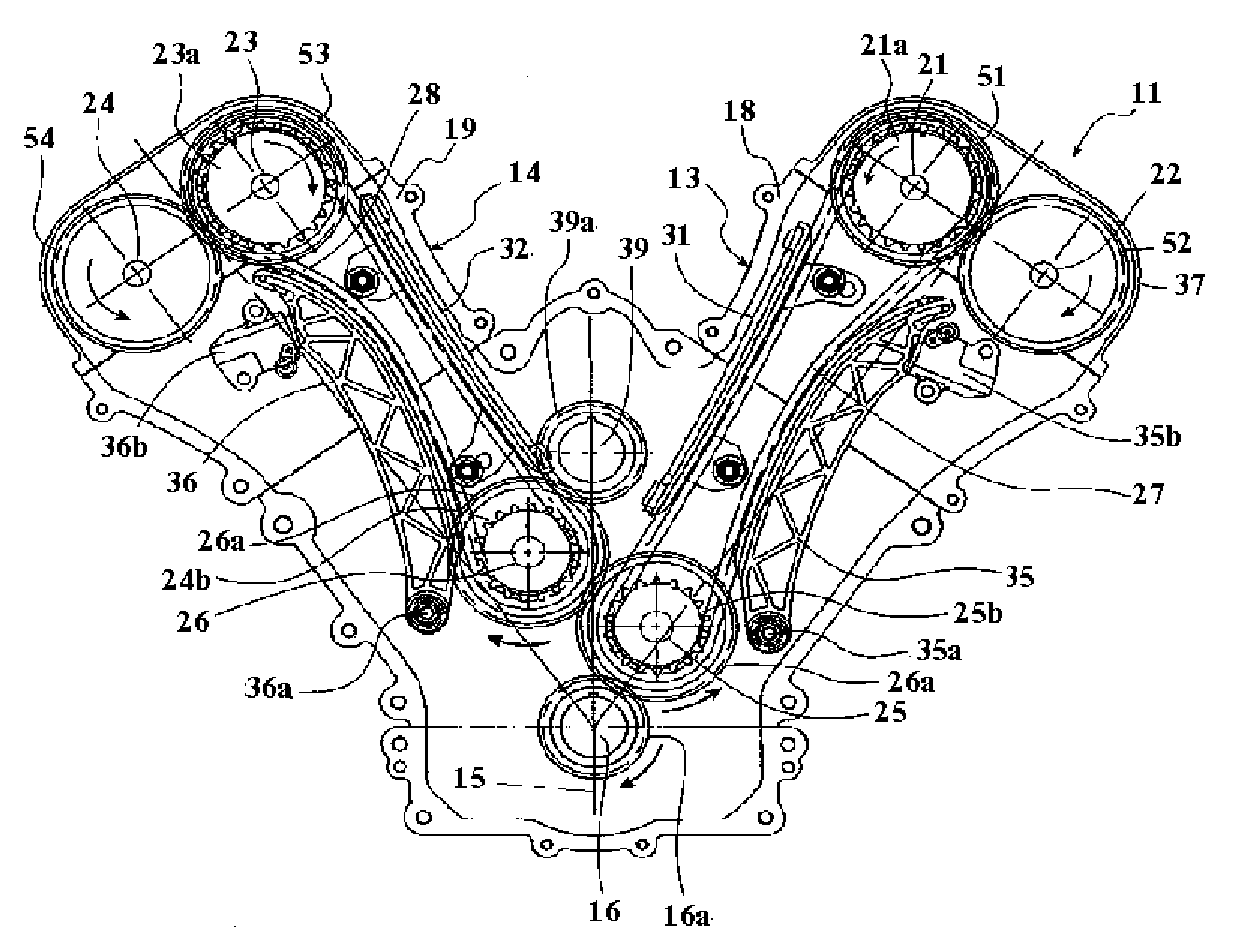
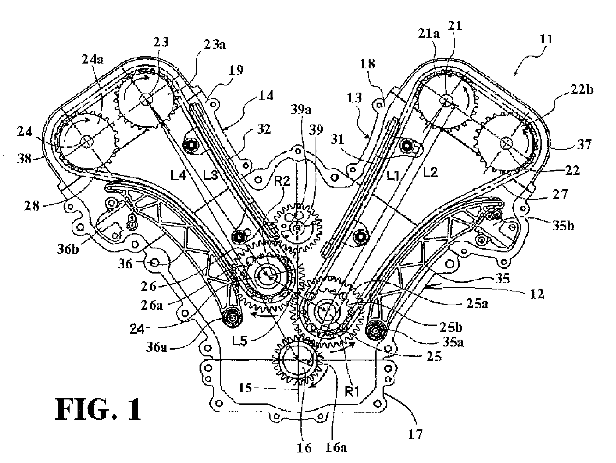
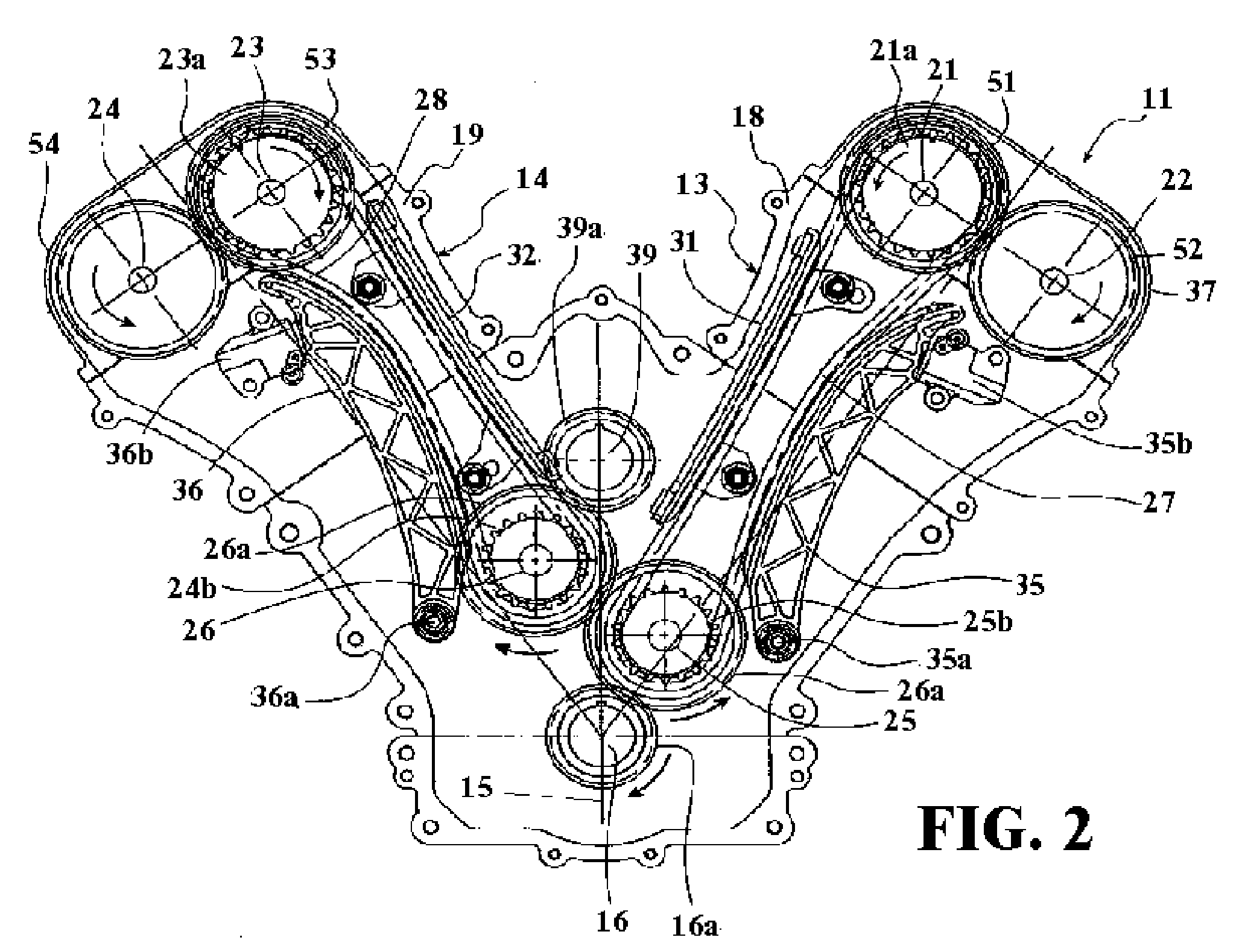
[0045] Referring now to the embodiment of FIG. 2, it presents several of the advantages of the embodiment already described and provides some additional features. Because of the similarity, components which are the same or generally similar are identified by the same numerals previously employed have been identified by the same reference numerals and will be described further only to make the construction and further advantages of this embodiment clear to those skilled in the art.

[0046] The main difference of this embodiment from FIG. 1 resides in the structure for driving the valve operating camshafts 21, 22, 23, and 24. To this end, the first valve operating camshafts 21 and 22 are respectively provided with first intermeshing gears 51 and 52 in meshing engagement with each other, and the second valve operating camshafts 23 and 24 are respectively provided with second valve gears 53 and 54 in meshing engagement with each other.

[0047] The first timing drive chain 27 is w...


PUM


Abstract

A number of embodiments of double overhead cam shaft V type engines wherein the drive arrangement for the camshafts permits not only a compact design but also one in which the timing loadings are decreased to improve engine life, performance and reduced servicing.

Description

BACKGROUND OF THE INVENTION [0001] The present invention relates to an internal combustion engine having cylinder bank portions arranged in a V-shaped configuration and more specifically to an improved mechanism for driving the respective valve operating camshafts of each of the cylinder bank portions and to provide a more compact engine. [0002] In V type engines and particularly those having pairs of overhead cam shafts for operating the valves of the cylinders of each bank, it is the practice to drive the cam shafts in timed relation to the engine crankshaft at one half crankshaft speed. [0003] Some examples of the way this has been previously done are disclosed in Published Japanese Application 2003-286845(A). As described and illustrated therein, a valve operating camshaft of one of the bank portions is driven by a crankshaft drive gear via an endless timing drive belt. In turn and a second camshaft drive gear shaft is in meshing engagement with the crankshaft drive gear to be d...

Claims


Application Information

Patent Timeline
IPC IPC(8): F01L1/02
CPCF01L1/022F01L1/024F01L1/026F01L1/16F01L1/185F01L2001/0537F02B75/22F16H7/18F16H2007/0872
Inventor OKAMOTO, YASUO
Owner YAMAHA MOTOR CO LTD
Learn More