
Sheet feeding device and image forming apparatus

a technology of feeding device and image forming apparatus, which is applied in the direction of thin material processing, instruments, article separation, etc., can solve the problem of taking a long time to raise the paper, and achieve the effect of reducing the time required to raise the paper

Inactive Publication Date: 2006-11-02
KYOCERA DOCUMENT SOLUTIONS INC
View PDF0 Cites 2 Cited by
  • Summary
  • Abstract
  • Description
  • Claims
  • Application Information

AI Technical Summary

Benefits of technology

[0008] An object of the present invention is to provide a sheet feeding device and image forming apparatus capable of reducing the time required to raise sheets of paper as well as stopping the sheets at an optimal feeding position.
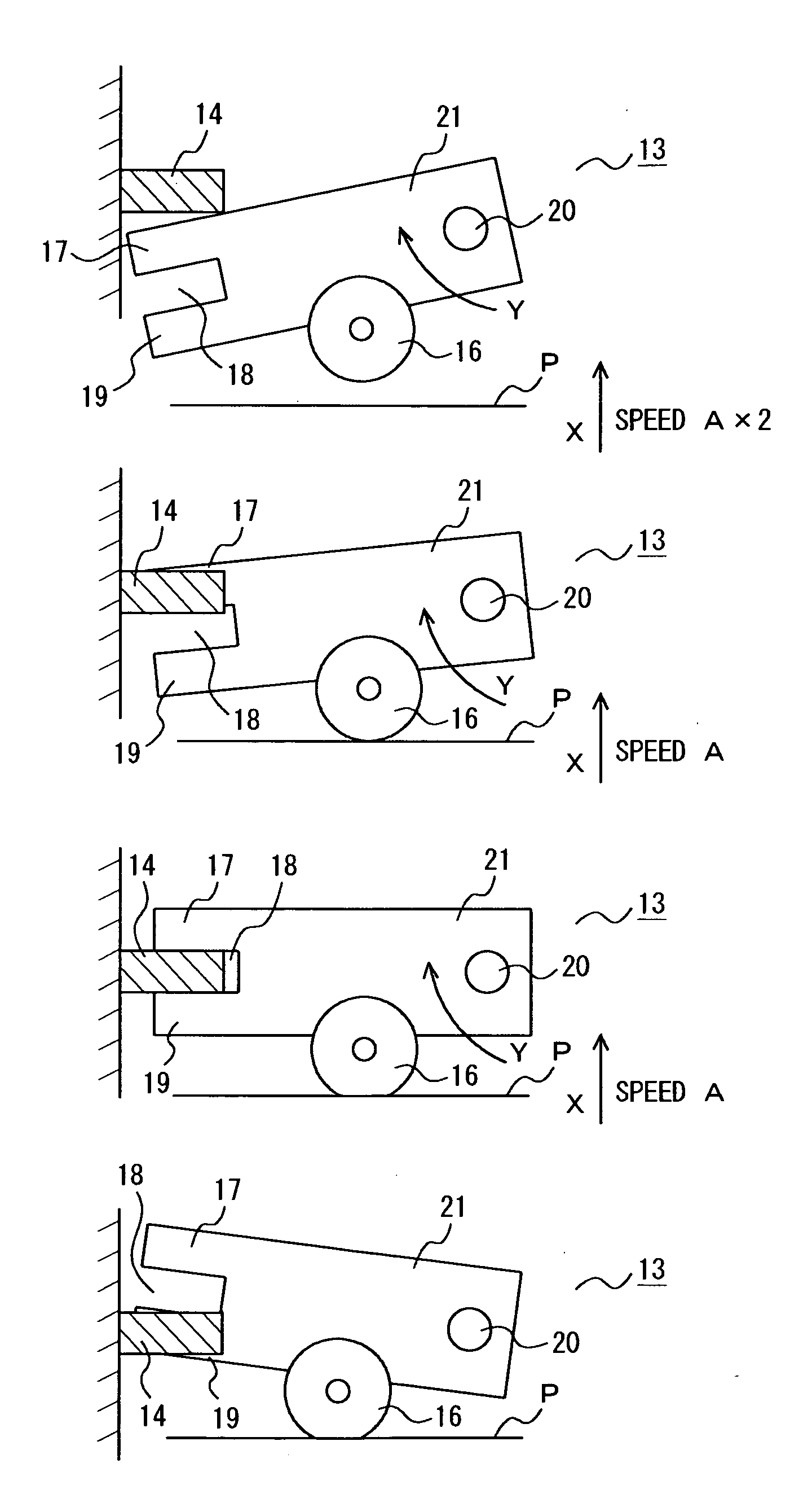
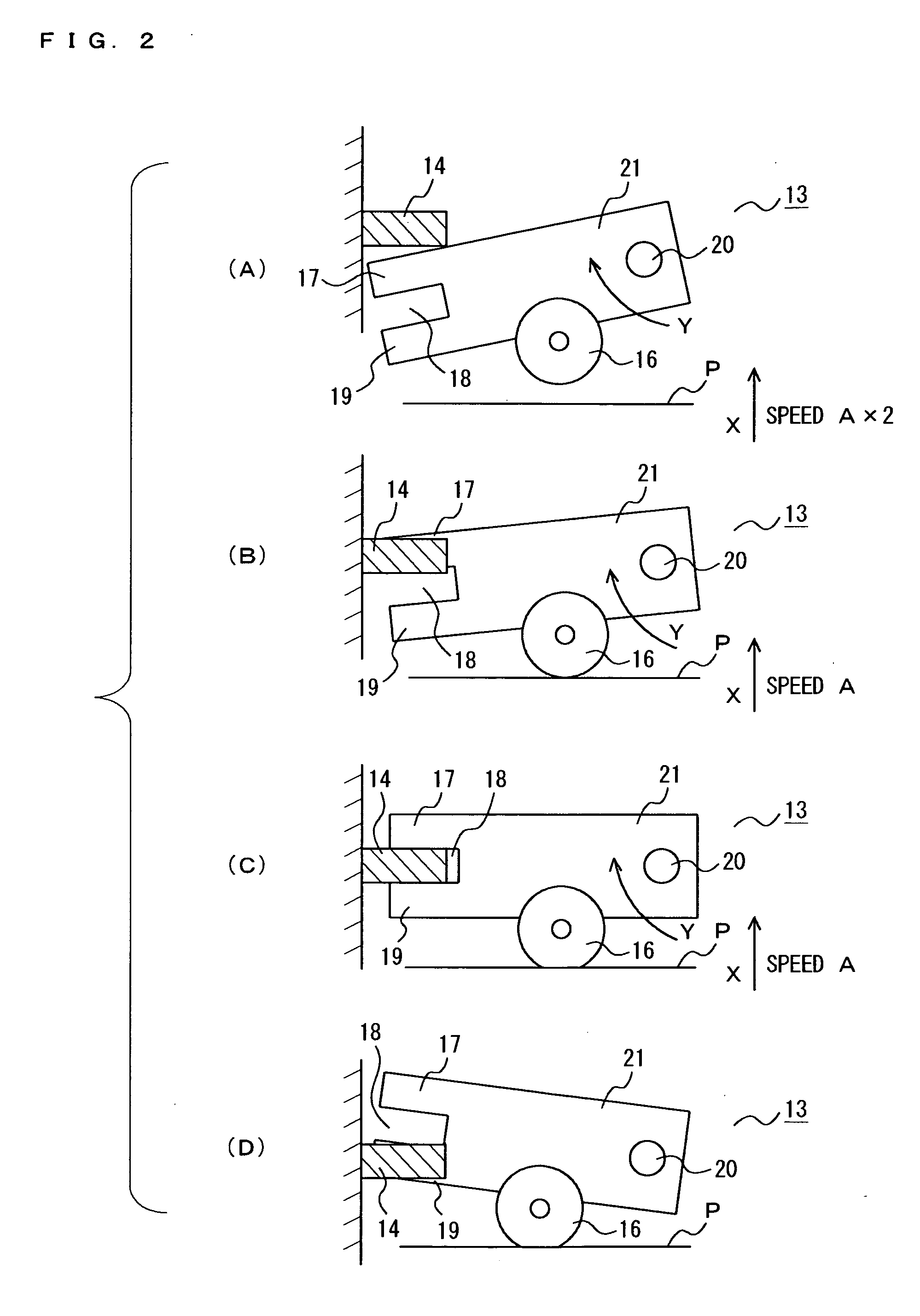
[0010] When the sheets of paper are raised according to the present invention, the sheets can be raised at high speed until reaching the predetermined position and raised at low speed from the predetermined position, thereby eliminating the risk of overrun of the lift motor or other elements.
[0011] As a result, the sheet feeding device and image forming apparatus capable of reducing the time required to raise the sheets as well as stopping the sheets at the optimal feeding position can be provided.

Problems solved by technology

However, according to JP 06-144643, when the residual quantity of paper to be fed is small, it takes some time to elevate the paper.
It would be possible to decrease time by raising the paper at high speed, however, excessively high speed may cause the lift motor or other elements to overrun, thereby creating the possibility for the sheets of paper not to stop at the optimal feeding position.

Method used


Image

  • Sheet feeding device and image forming apparatus
  • Sheet feeding device and image forming apparatus
  • Sheet feeding device and image forming apparatus

Examples


Embodiment Construction

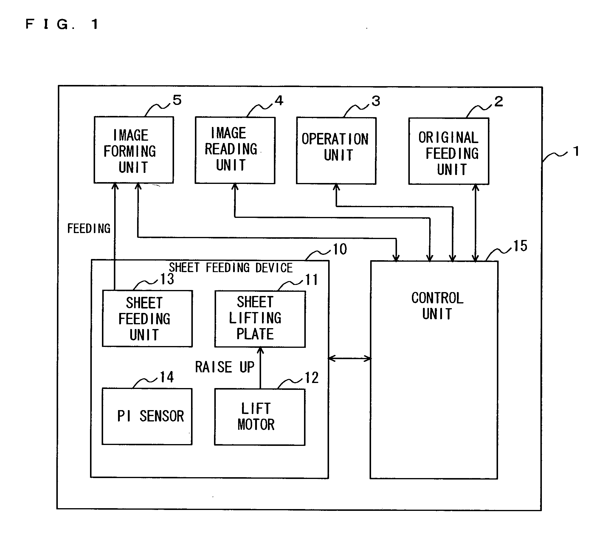
[0019] Referring to the drawings, an embodiment of the present invention will be described below. FIG. 1 is a block diagram illustrating the structure of the sheet feeding device and image forming apparatus according to the embodiment of the present invention. With reference to FIG. 1, the image forming apparatus 1 includes an operation unit 3 that is an interface through which users operate the image forming apparatus 1, an original feeding device 2 that automatically transfers an original document to a predetermined position at which images on the original are read, an image reading unit 4 in which a scanner reads images on the original, which is transferred by the original feeding device 2, at the predetermined reading position, an image forming unit 5 that forms the images read from the original document through the use of the image reading unit 4, a sheet feeding device 10 that feeds sheets of paper to the image forming unit 5, and a control unit 15 that controls the operation ...


PUM


Abstract

When the setting of sheet P is completed, a lift motor is actuated to raise the sheet P at Speed A×2. When a first light-blocking plate raised in association with the rise of the sheet P is detected by a PI sensor, the lift motor reduces its rotational speed to switch its lifting speed from high Speed A×2 to Speed A which is a half of the high speed. The Speed A does not cause the lift motor to overrun.

Description

BACKGROUND OF THE INVENTION [0001] 1. Field of the Invention [0002] This invention relates to a sheet feeding device and image forming apparatus, and in particular, relates to the sheet feeding device and image forming apparatus including a unit for raising sheets of paper to be fed through the use of a lift motor and other elements. [0003] 2. Description of Related Art [0004] In conventional sheet feeding devices, a lifting unit such as a lift motor is generally used to raise sheets of paper to an optimal feeding position according to the quantity of paper. [0005] A sheet feeding device that detects the residual quantity of paper by means of an elevation drive mechanism is disclosed in Japanese unexamined patent publication No. 06-144643, for example. [0006] According to JP 06-144643, a marker detecting sensor senses a sheet residual quantity detecting marker provided on an elevating path to detect the residual quantity of paper. Consequently, the sheets of paper are moved up to th...

Claims


Application Information

Patent Timeline
Patent Type & Authority Applications(United States)
IPC IPC(8): B65H3/06
CPCG03G15/6511
Inventor SHIBAHARA, MASAMI
Owner KYOCERA DOCUMENT SOLUTIONS INC
Learn More