Vacuum vessel, its method of manufacture, and electron emission display using the vacuum vessel

Inactive Publication Date: 2006-11-02
SAMSUNG SDI CO LTD
View PDF27 Cites 10 Cited by
  • Summary
  • Abstract
  • Description
  • Claims
  • Application Information

AI Technical Summary

Benefits of technology

[0011] In one exemplary embodiment of the present invention, a vacuum vessel is provided which inhibits the lowering of the degree of vacuum due to the out-gassing from the sealing member and includes a flattened glass bar and enhanced processing efficiency, and a method of manufacturing the vacuum vessel and an electron emission display using the vacuum vessel.

Problems solved by technology

However, since out-gassing occurs from the frit bar under a high temperature atmosphere, the interior of the vacuum vessel is contaminated, and the degree of vacuum thereof is lowered.
However, since the electron emission display has been recently large-scaled, the glass bar is liable to be twisted so that the flatness of the glass bar and the vacuum vessel is deteriorated, and the glass bar is easily broken, deteriorating the work efficiency.

Method used


Image

  • Vacuum vessel, its method of manufacture, and electron emission display using the vacuum vessel
  • Vacuum vessel, its method of manufacture, and electron emission display using the vacuum vessel
  • Vacuum vessel, its method of manufacture, and electron emission display using the vacuum vessel

Examples


Embodiment Construction

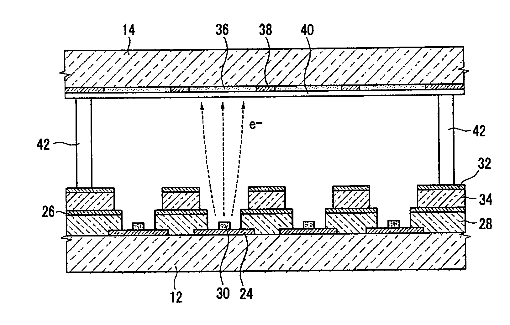
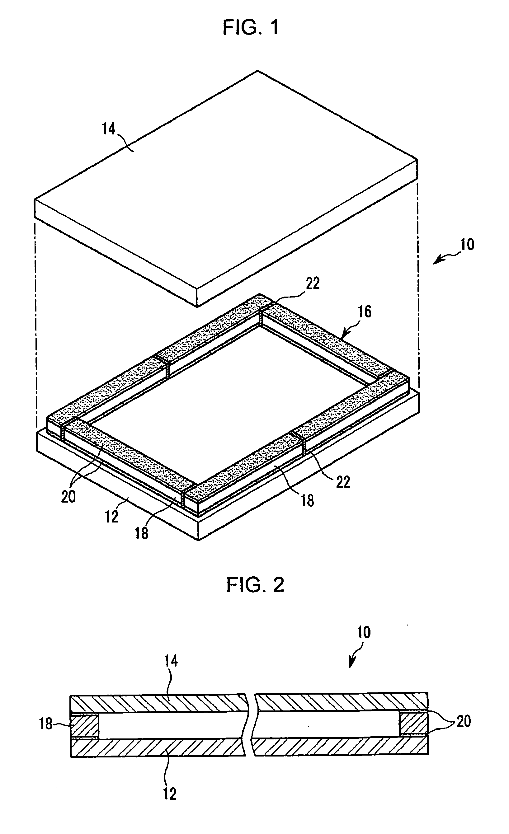
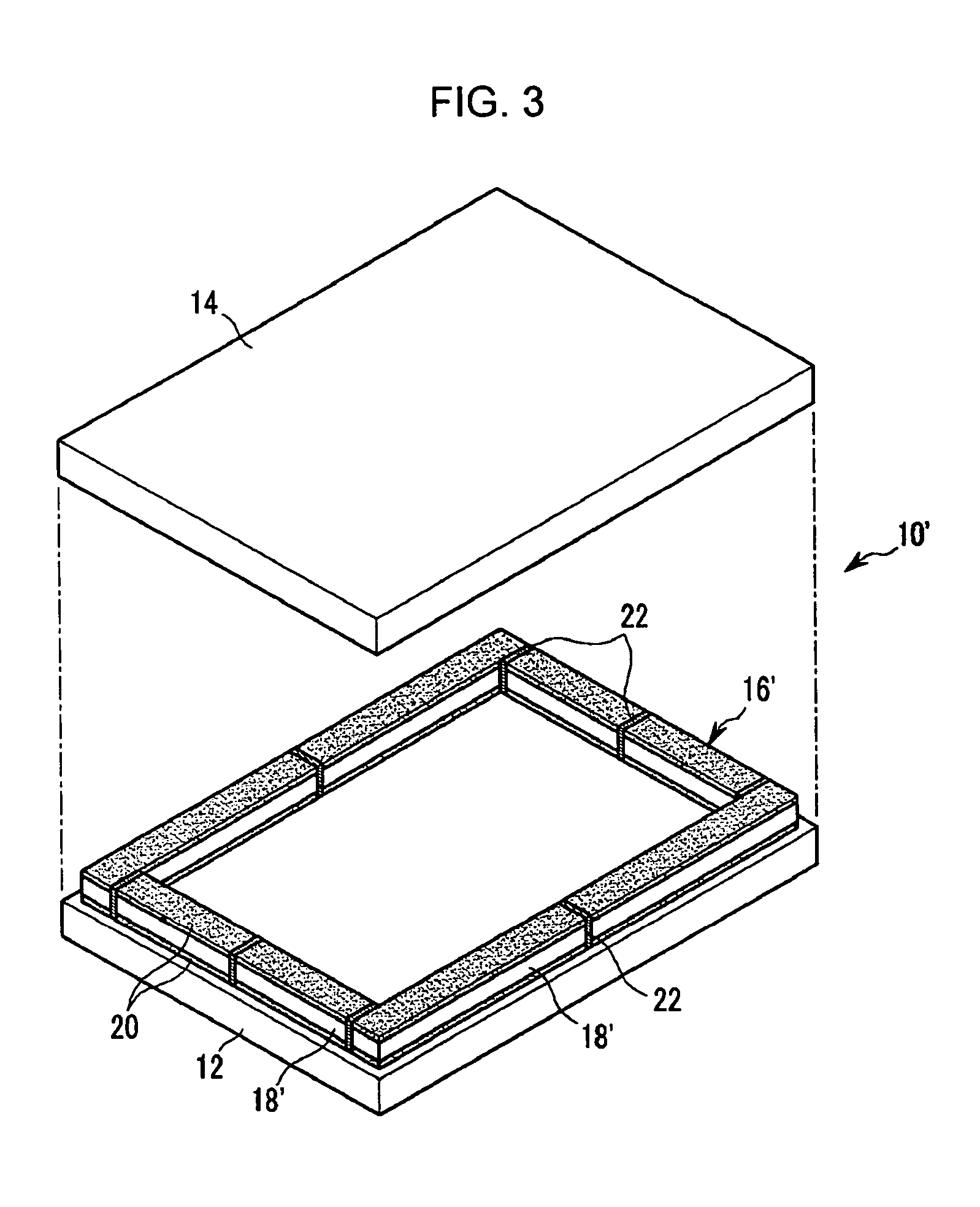
[0032] As shown in FIGS. 1 to 3, the vacuum vessel 10 according to an embodiment of the present invention includes first and second substrates 12 and 14 facing each other and spaced apart by a predetermined distance, and a sealing member 16 provided at the peripheries of the first and the second substrates 12 and 14 to seal them together. The interior of the vacuum vessel 10 is kept to a degree of vacuum of about 10−6 torr.

[0033] The sealing member 16 has two or more support frames 18 formed on at least one side of the first and the second substrates 12 and 14, adhesive layers 20 placed between the first substrate 12 and the support frames 18 as well as between the second substrate 14 and the support frames 18 to attach the two substrates 12 and 14 and the support frames 18 to each other, and a filler 22 provided at the interface between the neighboring support frames 18 to attach them together.

[0034] The support frames 18 are formed of glass, ceramics, a mixture of glass and cera...


PUM


Abstract

A vacuum vessel includes a first substrate, a second substrate facing the first substrate and spaced apart therefrom, and support frames mounted along the edges of the first and the second substrates. At least two support frames are separately formed on at least one side of the first and the second substrates. Adhesive layers are placed on a surface of the support frame facing the first substrate as well as on the opposite-surface of the support frame facing the second substrate to attach the two substrates and the support frames to each other. A filler is disposed between the neighboring support frames to prevent the vacuum leakage.

Description

CLAIM OF PRIORITY [0001] This application makes reference to, incorporates the same herein, and claims all benefits accruing under 35 U.S.C. §119 from an application for VACUUM VESSEL, METHOD OF MANUFACTURING THE VACUUM VESSEL, AND ELECTRON EMISSION DISPLAY DEVICE USING THE VACUUM VESSEL earlier filed in the Korean Intellectual Property Office on the 29th of Apr. 2005 and there, duly assigned Serial No. 10-2005-0035983. BACKGROUND OF THE INVENTION [0002] 1. Field of the Invention [0003] The present invention relates to a vacuum vessel, and more particularly, to a vacuum vessel in which first and second substrates are sealed together using support frames and adhesive layers, and a method of manufacturing the vacuum vessel and an electron emission display using the vacuum vessel. [0004] 2. Description of Related Art [0005] Generally, electron emission devices are classified into those using hot cathodes as an electron emission source, and those using cold cathodes as the electron emis...

Claims


Application Information

Patent Timeline
IPC IPC(8): H01J63/04H01J1/62
CPCF16J12/00H01J5/02H01J31/127H01J9/261H01J29/862H01J5/22H01J1/30
Inventor SEON, HYEONG-RAECHANG, DONG-SU
Owner SAMSUNG SDI CO LTD
Why Eureka
Try Eureka