

Waste container with buffering device
a buffering device and waste container technology, applied in the field of waste containers, can solve the problems of deterioration of gear and toothed parts, failure to provide the required cushioning effect, and requiring a considerable stepping force, and achieve the effect of easy repair
- Summary
- Abstract
- Description
- Claims
- Application Information
AI Technical Summary
Benefits of technology
Problems solved by technology
Method used
Image

Examples
first embodiment
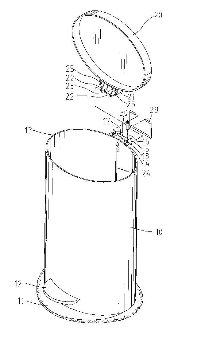
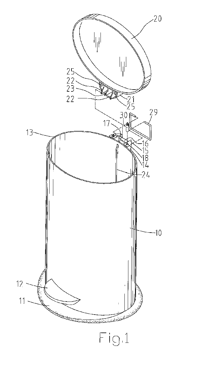
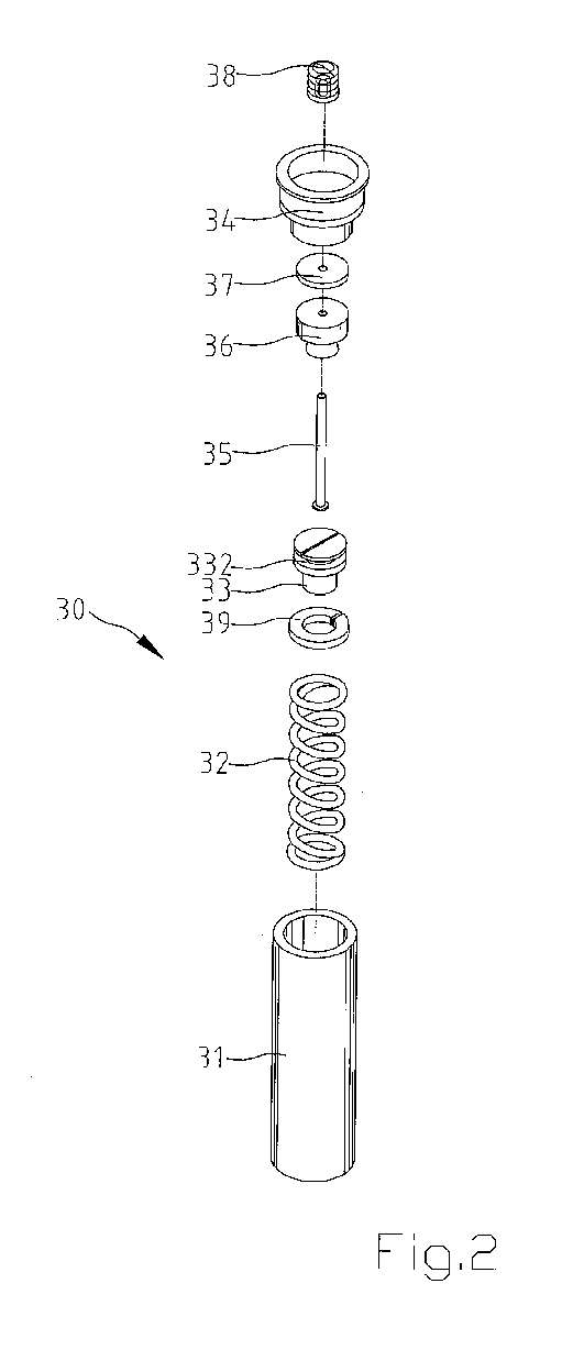
[0053] Referring to FIGS. 1 and 2, a waste container in accordance with the present invention comprises a container body 10, a cover 20, and a buffering device 30 mounted between the container body 10 and the cover 20 for buffering downward movement of the cover 20.
[0054] A base 11 may be mounted to a bottom of the container body 10. Further, a pedal 12 is mounted to a lower end of the container body 10 and spaced from the bottom of the container body 10. An opening 13 is defined in an upper end of the container body 10. Formed on an outer periphery of the upper end of the container body 10 is a connecting seat 14 that has a platform 15 on a top face thereof, with a central groove 16 being defined in the platform 15. A hole 17 is defined in each of two lateral walls delimiting the central groove 16. Further, a receptacle 18 is defined in each of two ends of the platform 15. As can be seen from FIG. 1, the receptacles 18 are located on two sides of the central groove 16 respectively....
second embodiment
[0067]FIG. 9 illustrates the invention, wherein the abutting sections 26 of the pivotal seat 21 of the cover 20 are in the form of ribs.
third embodiment
[0068]FIG. 10 illustrates the invention, wherein the abutting sections 27 of the pivotal seat 21 of the cover 20 are different from those in the previous embodiments. In this embodiment, the pivotal seat 21 includes a planar face that acts as the abutting sections 27.
[0069]FIG. 11 illustrates a third embodiment of the invention, wherein the buffering device 30 is provided on the cover 20. In particular, two receptacles 28 are defined in the pivotal seat 21 of the cover 20 for receiving the buffering device 30. Further, an abutting section 19 is provided on each of two sides of the platform 15 of the connecting seat 14 of the container body 10. A buffering effect is thus provided in a manner similar to the first embodiment.
PUM
 Abstract
Description
Claims
Application Information