Manifold compatibility electronic omni axis human interface

a human interface and multi-axis technology, applied in the field of multi-axis human interfaces, can solve the problems of inability to disclose a means, increase the complexity of information to be computed, and no practical application without specialized computers and specifically designed programs

Inactive Publication Date: 2006-11-09
GAMERUNNER +1
View PDF23 Cites 118 Cited by
  • Summary
  • Abstract
  • Description
  • Claims
  • Application Information

AI Technical Summary

Benefits of technology

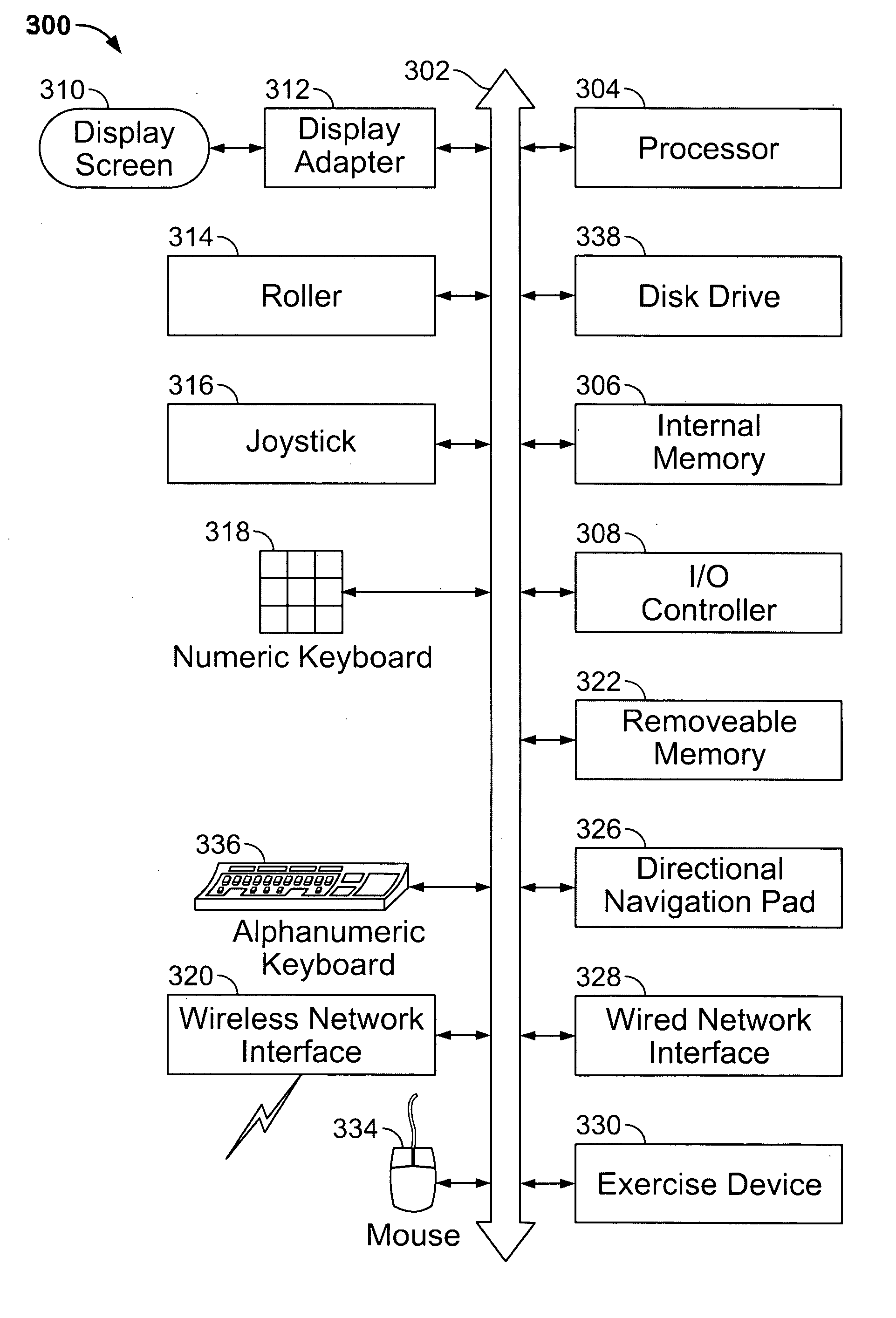
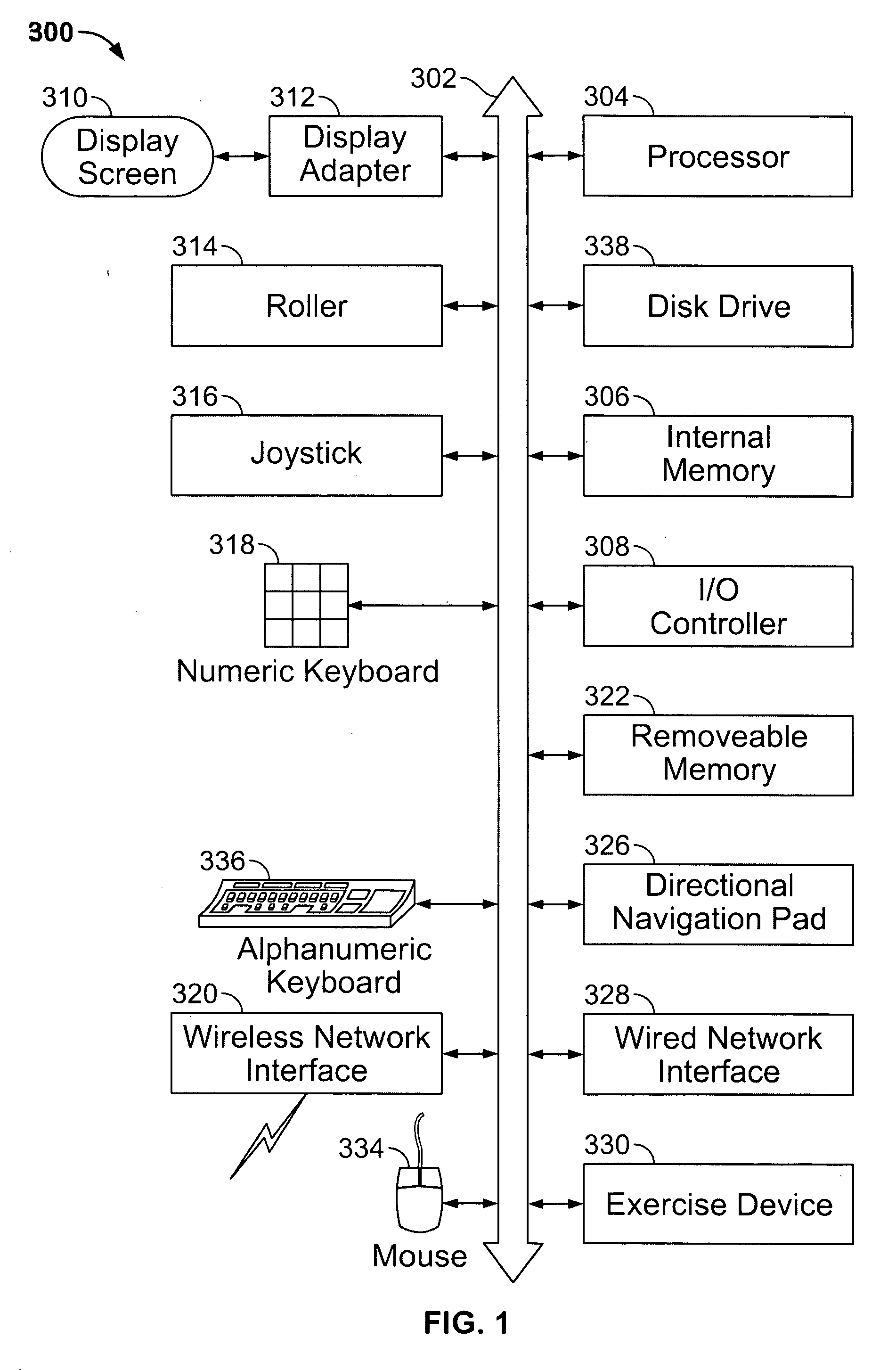
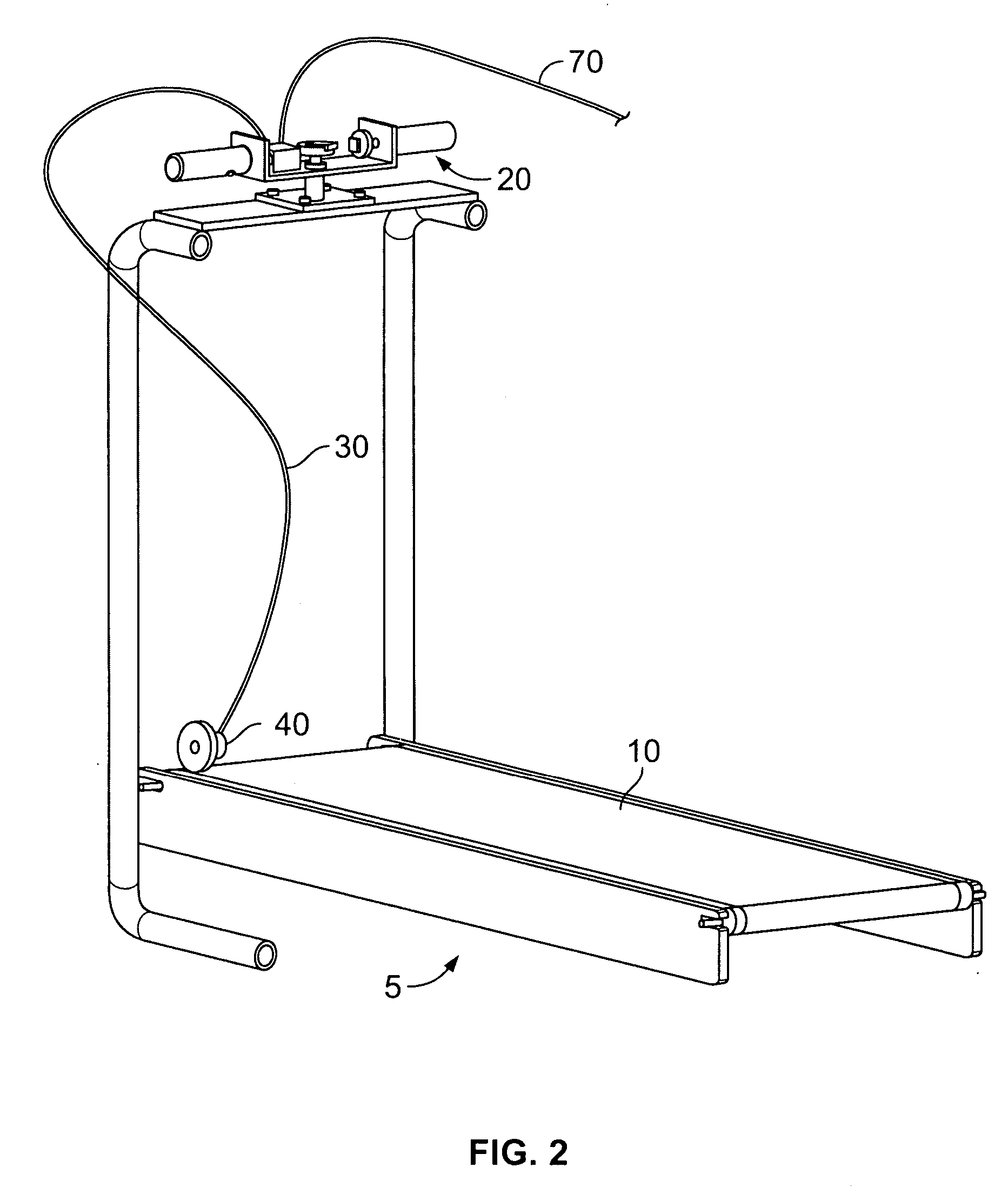
[0012] A manifold compatibility omni axis, electronic human interface device comprises a controller operatively coupled to an omni axis steering device having one or more attachments for motion detection, and a stationary fitness device operatively coupled to the controller. The controller comprises a re-centerer for re-centering one or more axis of movement, and a ratio processor for interpreting, transmitting, and adjusting one or more ratios for speed

Problems solved by technology

But these solutions typically either fail to disclose a means for accomplishing these goals, or describe various functions and feedback that are incompatible with existing systems currently in wide use.
In some solutions, the complexity of the information to be computed is increased to such an extent that there is no practical application without specialized computers and specifically designed programs.
As the bike leans however, it is not clear how the centrifugal forces of real riding are replicated in such a way as to keep a user from falling off of the bike in a deep turn.
Some solutions display a number of possible configurations as a means for arranging components that create a desired outcome, but fail to specify the mechanical or electronic inner workings of the device.
However, an analog transmission provides imprecise movement along various axis within computer software commonly in use today.
Some solutions mention digital transmission but fail to disclose a means for interfacing between the mechanical and electronic mechanisms comprising the computer gaming or training systems.
Some solutions require a separate computer

Method used


Image

  • Manifold compatibility electronic omni axis human interface
  • Manifold compatibility electronic omni axis human interface
  • Manifold compatibility electronic omni axis human interface

Examples


Embodiment Construction

[0026] Embodiments of the present invention are described herein in the context of a manifold compatibility electronic omni axis human interface. Those of ordinary skill in the art will realize that the following detailed description of the present invention is illustrative only and is not intended to be in any way limiting. Other embodiments of the present invention will readily suggest themselves to such skilled persons having the benefit of this disclosure. Reference will now be made in detail to implementations of the present invention as illustrated in the accompanying drawings. The same reference indicators will be used throughout the drawings and the following detailed description to refer to the same or like parts.

[0027] In the interest of clarity, not all of the routine features of the implementations described herein are shown and described. It will, of course, be appreciated that in the development of any such actual implementation, numerous implementation-specific decis...


PUM


Abstract

A manifold compatibility omni axis, electronic human interface device comprises a controller operatively coupled to an omni axis steering device having one or more attachments for motion detection, and a stationary fitness device operatively coupled to the controller. The controller comprises a re-centerer for re-centering one or more axis of movement, and a ratio processor for interpreting, transmitting, and adjusting one or more ratios for speed and other axis of movement. The controller is operatively coupled to a computer via a standard interface. The computer is configured to play a virtual reality program based at least in part on input from the controller. The controller is configured to mimic natural steering movements, making a user's physical movements with respect to the omni axis steering device and the stationary fitness device closely resemble movements in the virtual reality program.

Description

BACKGROUND OF THE INVENTION [0001] Many attempts have been made to increase the entertainment value of computer games and training systems. An area of extreme interest, both for designers and users of these systems, is that of physical immersion into a computer-generated world. A desire to have the sensation of truly being “in the game” has brought about the term “virtual reality”. The expression of this desire has been heavily pursued in both the entertainment and training industries. Examples are seen in the creation of sensors in hand or body gloves and helmets, infrared or other motion detecting devices, sensory replication devices, voice recognition and command, and display eyeglasses or goggles. [0002] Some solutions purport to be able to (1) detect the movement of a user, (2) provide feedback information to the user, and (3) be adapted to other computer gaming or training systems. But these solutions typically either fail to disclose a means for accomplishing these goals, or ...

Claims


Application Information

Patent Timeline
IPC IPC(8): A63B71/00A63F9/24A63F13/00G06F17/00
CPCA63B22/00A63B22/02A63B71/0622A63B2024/009A63B2225/20A63F2300/1062A63F13/06A63F2300/1006A63F2300/1018A63F2300/1037A63B2225/50A63F13/40A63F13/22A63F13/285A63F2300/64A63F2300/8082A63F13/23A63F2300/1025A63F2300/8005A63F13/245A63F13/57A63F13/816A63B24/0087
Inventor VAN NOLAND, MILTON CHARLESGARNER, JOY LUCETTE
Owner GAMERUNNER
Why Eureka
Try Eureka