Dynamically distributed, portal-based application services network topology for cellular systems

a dynamic distribution and application services technology, applied in the field of cellular system technologies, can solve the problems of affecting the presenting certain limitations and disadvantages for application developers, and disrupting the consistent “look & feel” of the interface provided to the handset user

Inactive Publication Date: 2006-05-25
GLENN PATENT GROUP
View PDF4 Cites 221 Cited by
  • Summary
  • Abstract
  • Description
  • Claims
  • Application Information

AI Technical Summary

Benefits of technology

[0014] Depending on the implementation, the present invention achieves one to a plurality of benefits or advantages: It reduces individual application development for each handset model enabling greater model coverage, better model penetration and faster time-to-market application service rollout. It drives cellular system operator revenue due to more bandwidth usage with uplink and downlink Pull and PUSH technology. It allows MMI and complete system upgrades across all handsets by simply upgrading the network application by either the application service provider or the cellular system operator. It creates a common application interface across all handsets which can be managed from an application server. Cellular system operators can easily augment and / or customize the “look and feel” of a given application. For example, the distributed portal-based application topology allows cellular system operator-specific content augmentations for ads, trademarks, logos, branding, etc. It provides the application service provider close alignment with cellular system operators as well as the handset providers. It enables the user database to be managed by the Application Service Provider (ASP) server and viewed directly from the server alleviating the requirement of an embedded database on the handset. Alternatively, a thin-database can be mirrored on the terminal. The portal-based, dynamically distributed processing architecture opens opportunities for strategic relationships with operators and dot.com providers. The present invention also affords cellular system operators the ability to provide phone content and have a presence on the phone, thereby, building an identity on the phone or other wireless device instead of only the handset manufacturer having an identity.

Problems solved by technology

These embedded or Java applications, however, do present certain limitations to application developers.
In addition, the interface provided by Java applications executed on cellular telephones is often quite different from the interface provided by native applications, disrupting a consistent “look & feel” of the interfaces provided to the handset user.
These cellular application topologies present certain limitations and disadvantages, however, to external application services providers and cellular system operators.
For example, web application servers, accessible via a WAP gateway, cannot identify and target particular cellular telephones, screen sizes or color plane depths, since they often serve personal computers and / or a large variety of wireless device types.
Moreover, the user experience associated with external application services may also suffer from the wide variety of wireless device types, each having varying capabilities and features, such as different screen types, color palettes, “look and feel” interfaces, and the like.
Still further, these cellular application topologies also present certain performance issues, since it is up to the external application service provider to decide the content delivery mode for all cellular systems, as opposed to leaving this decision to each cellular system operator who is in the best position to know the capabilities of the cellular system and the best mode for data or service delivery.
Existing cellular application topologies also limit the opportunities for custom-branding opportunities, since external application servers connected to packet data networks cannot distinguish between mobile stations associated with different wireless carriers.
Accordingly, the “look and feel” of a given application cannot be tailored or customized as desired by the cellular system operator.
In addition, given the extensive application processing facilities often required to host a given application service, installing application servers and other systems locally to the wireless carrier's operational centers and systems is also problematic.

Method used


Image

  • Dynamically distributed, portal-based application services network topology for cellular systems
  • Dynamically distributed, portal-based application services network topology for cellular systems
  • Dynamically distributed, portal-based application services network topology for cellular systems

Examples


Embodiment Construction

)

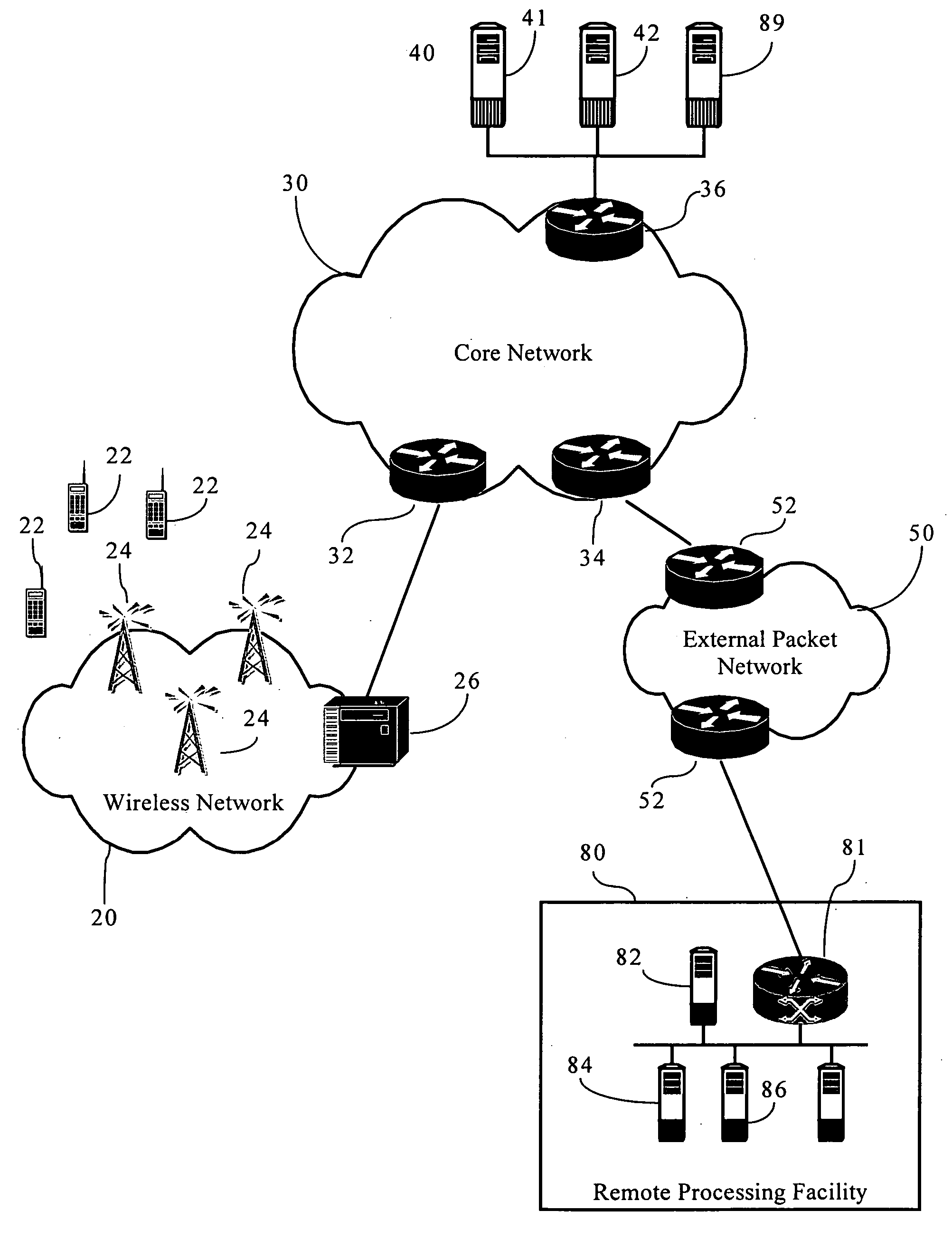
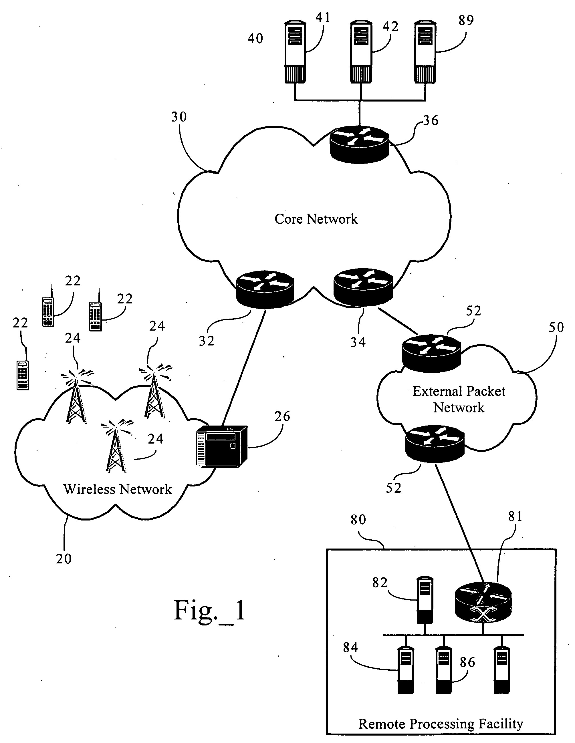
[0017]FIG. 1 is a functional block diagram illustrating a Dynamically Distributed Portal Based Application Network Topology according to an embodiment of the present invention. As FIG. 1 illustrates, in one implementation, the present invention operates in connection with at least one wireless network 20, core network 30, and external packet data network 50.

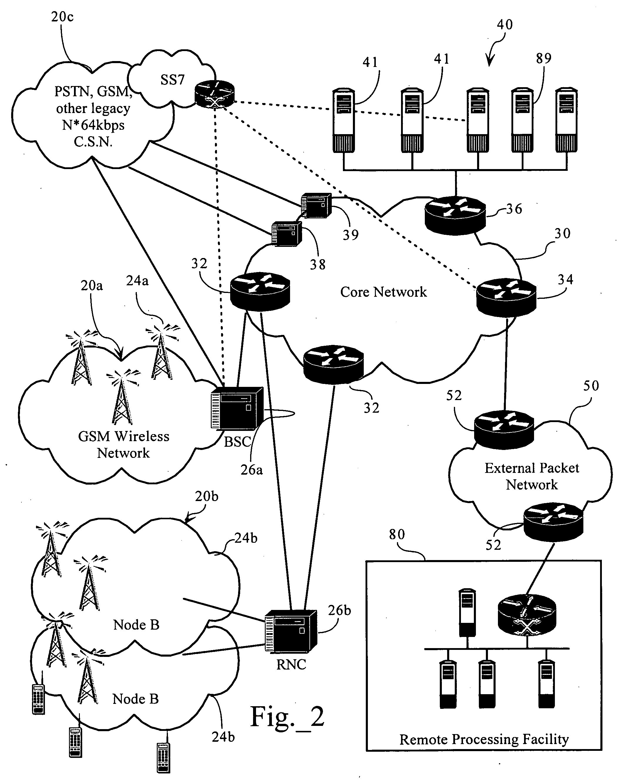
[0018] As discussed more fully below, wireless network 20 enables one or more wireless mobile stations 22 to establish connection with remote devices, such as other mobile stations, POTS telephones, and computing resources on external packet data network 50, for the transmission of voice or other data therebetween. In one embodiment, wireless network 20 includes at least one base station 24 (or other radio transmit / receive unit) operably connected to a base station controller 26 (e.g., a Base Station Controller (BSC), a Radio Network Controller (RNC), etc.).

[0019] The present invention can be deployed in connection with one to...


PUM


Abstract

Methods, apparatuses and systems directed to a portal-based, dynamically distributed application topology for cellular systems. The portal-based application topology, in one implementation, is an application architecture featuring strategic dynamic distribution of the man-machine interface (such as data acquisition and information presentation) and the backend processing aspects, of a particular application. In one implementation, all terminal interfacing aspects (such as data acquisition, data presentation) are formatted and handled by systems associated with a cellular system operator, as described below, while background processing is performed by a processing facility remote to the cellular system operator. In one implementation, the distributed application topology allows a mobile station, such as a cellular telephone, to simply act as a thin-client accessing an application server via a cellular systems operator's web portal for page-based interface screens.

Description

CROSS-REFERENCE TO RELATED APPLICATION [0001] The present application claims the benefit of U.S. Provisional Application Ser. No. 60 / 506,407 filed Sep. 26, 2003.FIELD OF THE INVENTION [0002] The present invention relates to cellular system technologies and, in one implementation, to a portal-based, dynamically distributed application services network topology for cellular systems. BACKGROUND OF THE INVENTION [0003] Cellular telephony is a type of full duplex wireless telecommunication in which a subscriber has a wireless connection from a mobile station (such as a cellular telephone) to a relatively nearby transceiver. The transceiver's span of coverage is called a cell. Each cell is served by its own radio telephone and control equipment, such as a base transceiver station. All the cells in a cellular system are connected to a Mobile Telephone Switching Office (MTSO) or Mobile Switching Center (MSC). The MTSO or MSC controls the switching between the Public Switched Telephone Netwo...

Claims


Application Information

Patent Timeline
Patent Type & Authority Applications(United States)
IPC IPC(8): H04M3/00H04BH04L29/06H04L29/08H04M3/493H04W4/00H04W84/04
CPCH04L29/06H04M3/493H04M3/4931H04M2207/18H04L69/329H04W4/00H04W84/042H04L67/04H04M2207/20H04L9/40
Inventor WEIGAND, DAVID L.
Owner GLENN PATENT GROUP
Why Eureka
Try Eureka