Virtual hinge

a hinge and virtual technology, applied in the field of hinges, can solve the problems of impracticality of removing the door for any desirable aesthetic purpose, the complexity of modern mechanical hinges, and the inability to meet the needs of cleaning or refurbishing,

Inactive Publication Date: 2006-11-16
DANKO PETER
View PDF21 Cites 13 Cited by
  • Summary
  • Abstract
  • Description
  • Claims
  • Application Information

AI Technical Summary

Benefits of technology

[0029] A method for providing an alternative to hinges for hanging a door, either vertically or horizontally, involves the use of adjacent interacting magnetic fields that in effect create a rotational axis similar to that formed by a physical hinge. A virtual hinge involves pairs of magnets that are inserted along a frame member and its respective door. These pairs of magnets are in an approximate distance such that their respective magnetic fields interact to behave much the same way a hinge works when a door is opened or closed. The magnetic fields of the virtual hinge also may behave as a spring to act as a self closing mechanism. The virtual hinge may be instantly installed or removed as desired or reversed to hang on an opposite stile, the vertical or upright framing pieces of the cabinet face frame.

Problems solved by technology

In recent years, modern mechanical hinges have grown in complexity, and the idea of hiding hinges for decorative purposes has evolved in many directions, some of which are known in the trade as European hinges, 35 mm hinges, and SOSS hinges.
Tasks requiring removal of the door from the structure, e.g. for cleaning or refurbishing, may be tedious because of the fastened nature of the door with respect to the hinged coupling.
Moreover, once a door is attached to a frame, it is impractical to remove the door for any desirable aesthetic purposes because of the visibility of the hinge and / or the holes in the frame where the hinge was fastened.
While the state of the art includes magnets that can lock a door to its support, these magnets do not have any appreciable potential to return the door to its closed state or otherwise support the door without any structural coupling between the door and surrounding structure.

Method used


Image

  • Virtual hinge
  • Virtual hinge
  • Virtual hinge

Examples


Embodiment Construction

[0038] The particulars shown herein are by way of example and for purposes of illustrative discussion of the embodiments of the present invention only and are presented in the cause of providing what is believed to be the most useful and readily understood description of the principles and conceptual aspects of the present invention. In this regard, no attempt is made to show structural details of the present invention in more detail than is necessary for the fundamental understanding of the present invention, the description taken with the drawings making apparent to those skilled in the art how the several forms of the present invention may be embodied in practice.

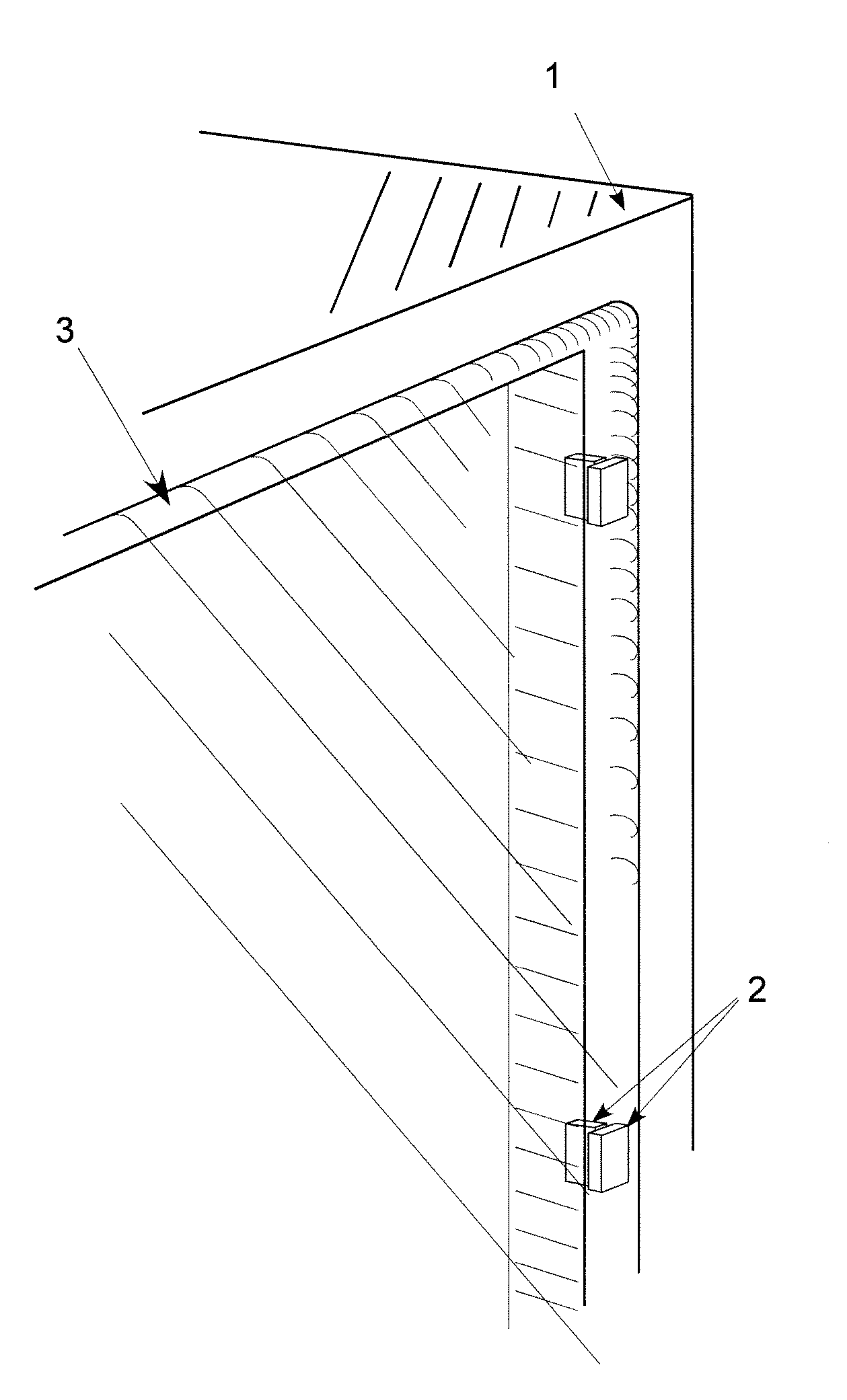
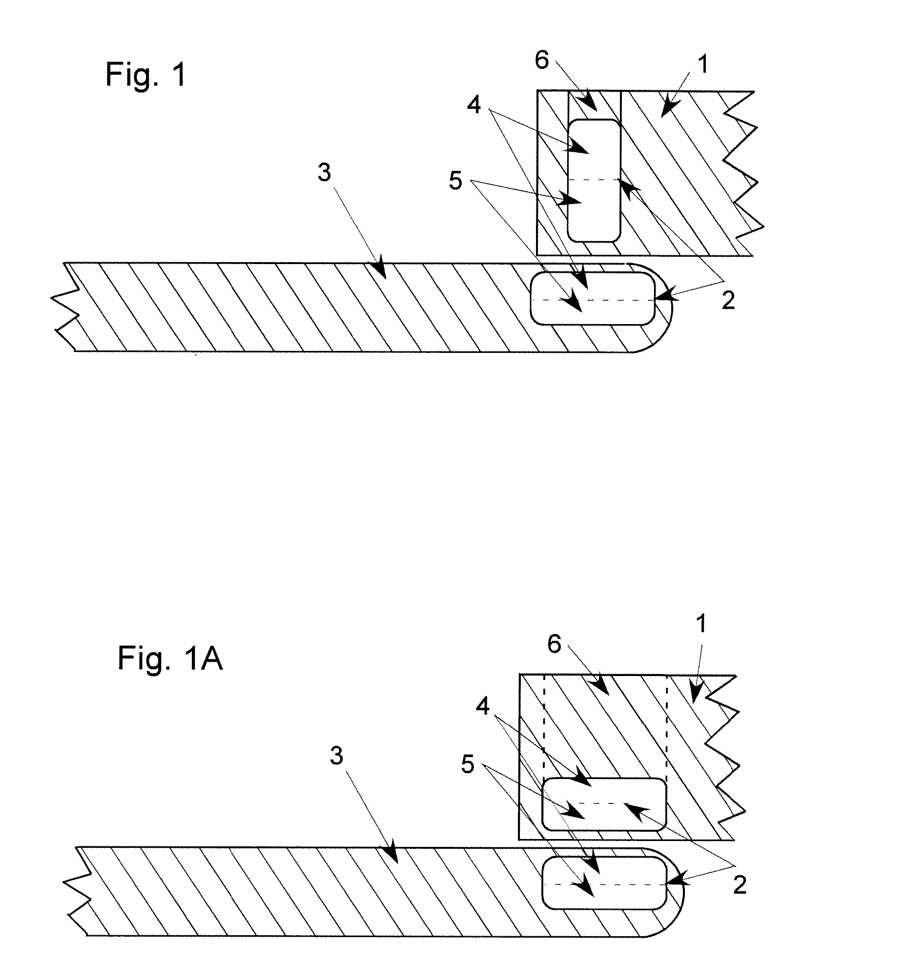
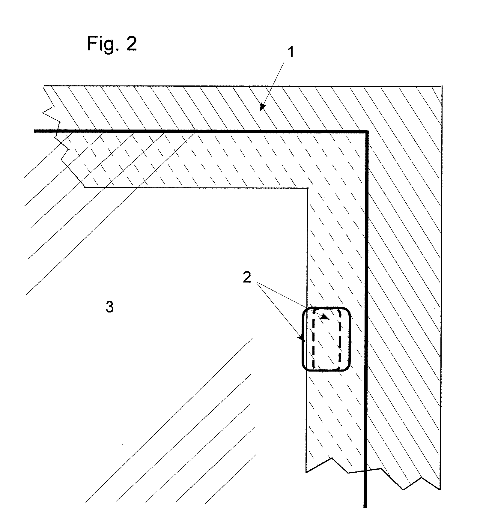
[0039] Referring now to FIGS. 1-6, preferred exemplary embodiments of the present invention are shown with three basic elements that cooperate to create a structure that can assume the role of a container 1 with a cover 3. In each depiction of the embodiment, cover 3 is magnetically coupled to container 1 using magnets ...


PUM


Abstract

A support system includes a frame member and a cover magnetically coupled to one another proximate an edge of the cover and in an aligned state. The cover is rotatable with respect to the frame member without any structural coupling therebetween while the frame member and cover remain substantially in the aligned state. A method of supporting a cover with respect to a frame includes magnetically attracting the cover and frame to each other proximate an edge of the cover.

Description

CROSS-REFERENCE TO RELATED APPLICATION [0001] The benefits of Provisional Application No. 60 / 680,020 filed May 12, 2005 and entitled “Virtual Hinge” are claimed under 35 U.S.C. § 119(e), and the entire contents of this provisional application are expressly incorporated herein by reference thereto.FIELD OF THE INVENTION [0002] The invention relates primarily to product design and, in particular, a hinging device that utilizes magnets configured for the magnetic coupling of a cover to a support, used for example to form cabinets, boxes and other coverable spaces. BACKGROUND OF THE INVENTION [0003] Structural coupling devices such as hinges have existed for many centuries. The concept of a mechanical hinge largely involves extended parts pivoting around a pin. In recent years, modern mechanical hinges have grown in complexity, and the idea of hiding hinges for decorative purposes has evolved in many directions, some of which are known in the trade as European hinges, 35 mm hinges, and ...

Claims


Application Information

Patent Timeline
Patent Type & Authority Applications(United States)
IPC IPC(8): E05D11/10
CPCE05D1/00Y10T16/5401Y10T16/52E05Y2201/46E05D1/06
Inventor DANKO, PETER
Owner DANKO PETER
Why Eureka
Try Eureka