Cigarette packing machine for producing rigid hinged-lid packets

Inactive Publication Date: 2006-11-16
GD SPA
9 Cites 8 Cited by

AI-Extracted Technical Summary

Problems solved by technology

Though producing good-quality packets of cigarettes, special machines of the above type are expensive to produce, have a low output r...

Method used

[0046] Packing machine 1 as described above produces rigid, short-hinge packets of cigarettes, has a high output rate (up to 500-600 packets a minute), and is cheap and easy to produce, by closely resembling a standard packing machine for producing conv...

Benefits of technology

[0009] It is an object of the present invention to provide a cigarette packing machine for producin...

Abstract

A cigarette packing machine for producing rigid, hinged-lid, short-hinge packets of cigarettes; the packing machine has a fourth packing wheel which receives wrapped groups of cigarettes from a third transfer wheel at a third transfer station, receives collars from a first feed line at an input station upstream from the third transfer station, and folds each collar into a tube about a respective wrapped group of cigarettes; the packing machine also has a fifth packing wheel which, at a fourth transfer station, receives each wrapped group of cigarettes and the respective collar together with a respective blank supplied by a second feed line, folds the blank about the wrapped group of cigarettes to form an outer package, and releases the packets of cigarettes at a fifth transfer station.

Application Domain

Packaging cigaretteWrapper folding/bending apparatus +1

Technology Topic

Cigarette packEngineering +1

Image

  • Cigarette packing machine for producing rigid hinged-lid packets
  • Cigarette packing machine for producing rigid hinged-lid packets
  • Cigarette packing machine for producing rigid hinged-lid packets

Examples

  • Experimental program(1)

Example

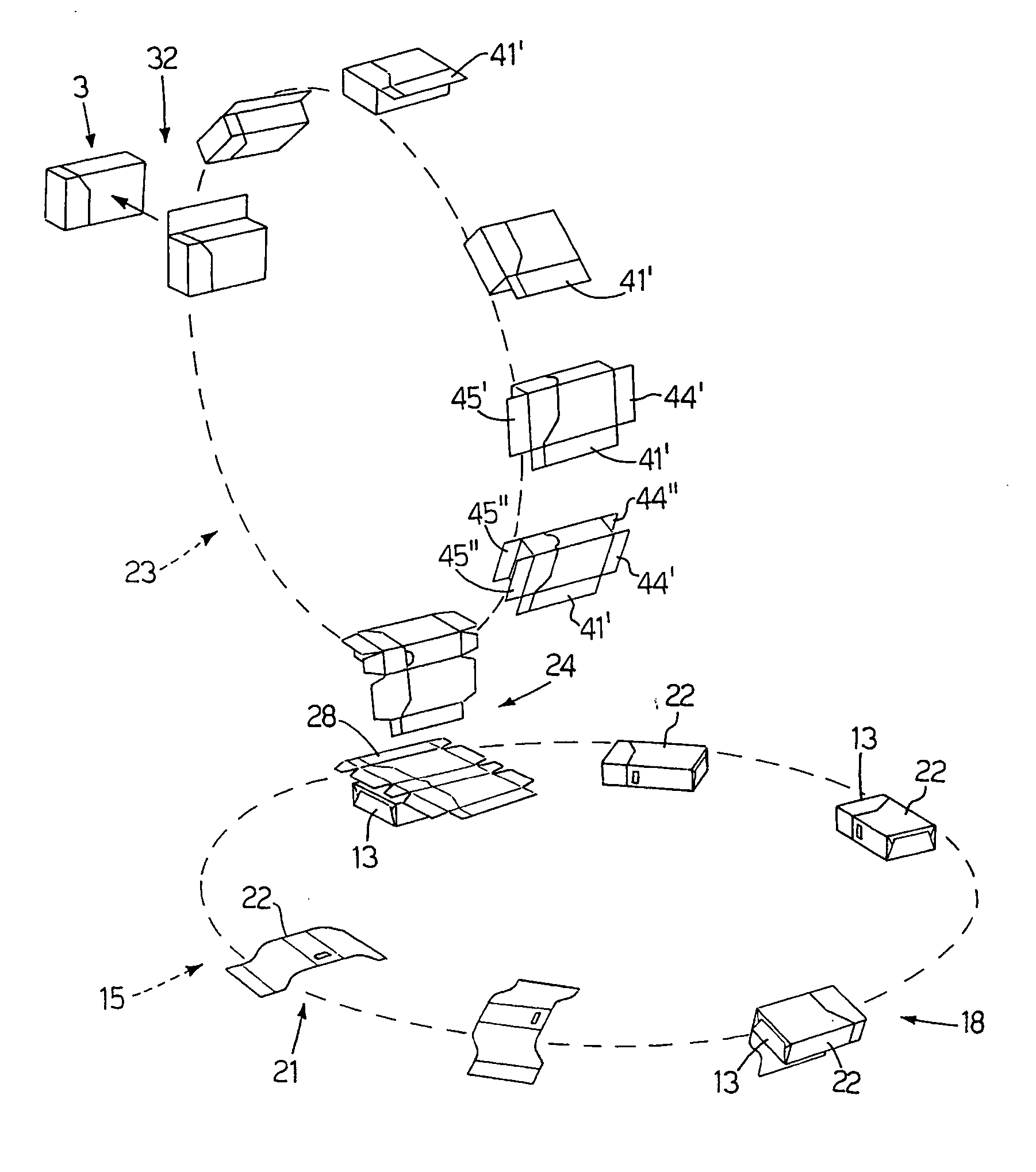
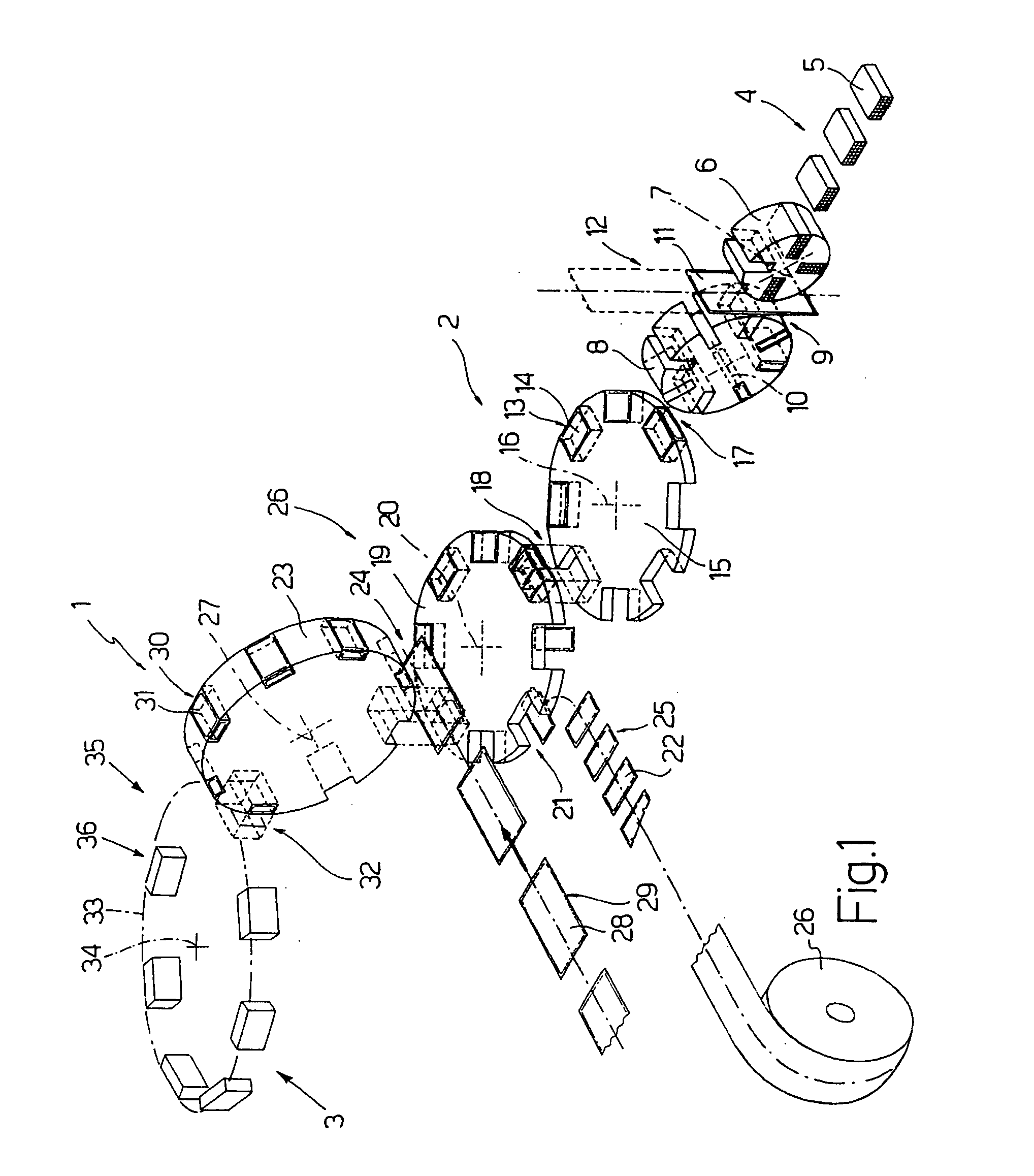
[0019] Number 1 in FIG. 1 indicates as a whole a cigarette packing machine comprising a packing portion 2 and an output portion 3.
[0020] Packing portion 2 comprises a known line 4 (shown only partly) for forming groups 5 of cigarettes; and a first transfer wheel 6 rotating in steps about a respective horizontal axis of rotation 7 to receive groups 5 successively, and transfer groups 5 to a second packing wheel 8 at a transfer station 9. Second packing wheel 8 is mounted to rotate in steps about a respective axis of rotation 10 parallel to axis of rotation 7, and receives groups 5 of cigarettes successively, each together with a respective sheet 11 of foil packing material supplied to transfer station 9 by a feed line 12. Second packing wheel 8 folds each sheet 11 of packing material about respective group 5 of cigarettes to form a wrapped group 13, in which group 5 of cigarettes is enclosed in a so-called inner wrapping 14.
[0021] Packing portion 2 also comprises a third transfer wheel 15 rotating in steps about a respective vertical axis of rotation 16 crosswise to axis of rotation 7, and which receives wrapped groups 13 successively from second packing wheel 8 at a transfer station 17. At a transfer station 18, third transfer wheel 15 feeds wrapped groups 13 to a fourth packing wheel 19 rotating in steps about a respective axis of rotation 20, parallel to axis of rotation 16, and structurally identical to third transfer wheel 15. On the periphery of both third transfer wheel 15 and fourth packing wheel 19, each rectangular parallelepiped-shaped wrapped group 13 is positioned on edge, i.e. with a minor lateral surface facing outwards, and with its longitudinal axis (always parallel to the cigarette axes) crosswise to axes of rotation 16 and 20 and tangential with respect to the periphery of relative transfer wheel 15 and packing wheel 19. Fourth packing wheel 19 and third transfer wheel 15 overlap at transfer station 18, and wrapped groups 13 are transferred from third transfer wheel 15 to fourth packing wheel 19 in a vertical movement parallel to axes of rotation 16 and 20.
[0022] At an input station 21 upstream from transfer station 18, fourth packing wheel 19 successively receives creased cardboard collars 22, each of which is folded about a respective wrapped group 13 before being transferred, together with respective wrapped group 13, to a fifth packing wheel 23 at a transfer station 24. Collars 22 are fed to input station 21 by a known feed line 25. More specifically, collars 22 are formed in known manner from a continuous strip of cardboard unwound off a reel 26.
[0023] Fifth packing wheel 23 is an output wheel of packing portion 2, is mounted to rotate in steps about a respective horizontal axis of rotation 27 parallel to axis of rotation 7, receives each wrapped group 13 and respective collar 22 together with a respective blank 28 fed to transfer station 24 by a feed line 29, and folds each blank 28 about respective wrapped group 13 to form a packet 30, in which wrapped group 13 is housed inside an outer package 31 formed by folding blank 28.
[0024] Packets 30 are fed successively from fifth packing wheel 23 to an input of output portion 3 at a transfer station 32. More specifically, each packet 30 reaching transfer station 32 is positioned flat on the periphery of fifth packing wheel 23, i.e. with a major lateral surface of relative wrapped group 13 facing outwards, and with the longitudinal axis of relative wrapped group 13 (parallel to the relative cigarettes) parallel to axis of rotation 27 of fifth packing wheel 23.
[0025] Output portion 3 comprises a sixth transfer wheel 33 rotating in steps about a respective horizontal axis of rotation 34 crosswise to axis of rotation 27 of fifth packing wheel 23. At transfer station 32, sixth transfer wheel 33 receives packets 30 successively from fifth packing wheel 23, and transfers packets 30 to a drying area 35 (shown schematically) at a transfer station 36. Drying area 35 constitutes an output of packing machine 1, and feeds packets 30 to a follow-up cellophaning machine (not shown) which applies an overwrapping of transparent plastic material about each packet 30.
[0026]FIGS. 2, 3 and 4 show a packet 30 produced on packing machine 1 as described above. More specifically, packet 30 is a “short-hinge” type, the outer package 31 of which comprises a cup-shaped container 37 having an open top end 38 (FIGS. 3 and 4); and a cup-shaped lid 39 hinged to container 37 along a hinge 40 (FIG. 4) to rotate, with respect to container 37, between an open position (FIGS. 3 and 4) and a closed position (FIG. 2) respectively opening and closing open top end 38. The bottom edge of lid 39 (and therefore the top edge of container 37, which is the same shape as the bottom edge of lid 39) is preferably S-shaped, so that lid 39 is shorter in height close to hinge 40.
[0027] When lid 39 is in the closed position, outer package 31 is parallelepiped-shaped, and comprises a vertical rear wall 41; a vertical front wall 42 opposite and parallel to rear wall 41 (shown in FIG. 4); two opposite parallel vertical lateral walls 43 (only one shown in FIGS. 2 and 3); a horizontal bottom wall 44 (FIG. 4); and a horizontal top wall 45 (FIG. 2) opposite and parallel to bottom wall 44. Front wall 42 and rear wall 41 are smaller than lateral walls 43; and hinge 40 of lid 39 is horizontal and located on rear wall 41.
[0028] Outer package 31 has four longitudinal edges 46 defined between lateral walls 43 and front and rear walls 42 and 41; and eight transverse edges 47 defined between top and bottom walls 45 and 44 and lateral walls 43, front wall 42, and rear wall 41. In the FIG. 2-4 embodiment, longitudinal edges 46 and transverse edges 47 are all square. In different embodiments not shown, at least some of longitudinal edges 46 or at least some of transverse edges 47 are rounded or bevelled. For example, longitudinal edges 46 may all be non-square, rounded or bevelled edges, or some transverse edges 47 may be non-square, rounded or bevelled edges (as in the packet of cigarettes described in Patent Application EP-A1-0764595); or some longitudinal edges 46 and some transverse edges 47 may be non-square, rounded or bevelled edges, so as to have both non-square, rounded or bevelled longitudinal edges 46 and transverse edges 47.
[0029] In a different embodiment not shown, packet 30 may resemble the packet of cigarettes described in Patent Application EP-A1-1066205; in which case, rear wall 41 and front wall 42 are outwardly convex, and each have a flat central portion, and two curved creased lateral bands connecting the flat central portion to lateral walls 43 at respective sharp, non-square longitudinal edges 46.
[0030] Collar 22 is folded into a tube about wrapped group 13, and is positioned inside outer package 31 so as to project partly from open top end 38 of container 37 and engage an inner surface of lid 39 when lid 39 is in the closed position. As shown in FIG. 6, collar 22 comprises a rear wall 48, which is positioned contacting an inner surface of rear wall 41 of outer package 31; a front wall 49, which is positioned contacting an inner surface of front wall 42 of outer package 31; and two lateral walls 50, which are positioned contacting respective inner surfaces of lateral walls 43 of outer package 31.
[0031] The purpose of collar 22 is to keep lid 39 closed by requiring the application of a certain amount of force to open lid 39. For which purpose, front wall 49 of collar 22 has a horizontal slit 51 (FIG. 3), and the bottom edge of front wall 42 of lid 39 has a tab 52 (FIG. 4) projecting inwards of lid 39, and which, when lid 39 is in the closed position, releasably engages slit 51 to hold lid 39 in the closed position.
[0032] In a different embodiment not shown, collar 22 has no rear wall 48, and is folded into a U about wrapped group 13.
[0033] As stated, outer package 31 of each rigid packet 30 of cigarettes is formed by folding a blank 28 as shown in the unfolded configuration in FIG. 5, in which the parts of blank 28 are indicated, where possible, using the same reference numbers, with superscripts, as for the corresponding parts of outer package 31.
[0034] Blank 28 has two transverse fold lines 53, and a number of longitudinal fold lines 54 defining, between the two transverse fold lines 53, a panel 41′ forming an inner portion of rear wall 41; a panel 43′ forming a first lateral wall 43; a panel 42′ forming front wall 42; a panel 43″ forming a second lateral wall 43; and a panel 41″ forming an outer portion of rear wall 41.
[0035] Panel 43′ has two tabs 44′ and 45′, which are located at opposite ends of panel 43′, are separated from panel 43′ by the two transverse fold lines 53, and form outer portions of bottom wall 44 and top wall 45 respectively. Panel 43″ has two tabs 44″ and 45″, which are located at opposite ends of panel 43″, are separated from panel 43″ by the two transverse fold lines 53, and form inner portions of bottom wall 44 and top wall 45 respectively. Panel 42′ and panel 41″ each have two tabs 55, 56, which are located at opposite ends of panel 42′, 41″, are separated from panel 42′, 41″ by the two transverse fold lines 53, and are glued to the inside of bottom wall 44 and top wall 45.
[0036] Panel 41′ and panel 41″ have a fold line 40′ and a fold line 40″ respectively. When panel 41′ is superimposed on and glued to panel 41″ to form rear wall 41, fold lines 40′ and 40″ are superimposed to define hinge 40 of lid 39. A cut line 57 extends from fold line 40′ to fold line 40″ and, substantially parallel to transverse fold lines 53, across panels 43′, 42′ and 43″ to separate the part of blank 28 forming container 37 from the part forming hinged lid 39. On panel 42′, cut line 57 is preferably shaped to define tab 52 on one side, and, on the other, a cavity complementary in shape to tab 52.
[0037] The folding sequence performed by packing machine 1 in FIG. 1 to form outer package 31 of the rigid packet 30 of cigarettes in FIG. 2 will now be described with particular reference to FIG. 7. For the sake of simplicity, the folding operations performed by packing machine 1 will be described with reference to one wrapped group 13 of cigarettes fed to fourth packing wheel 19 at transfer station 18.
[0038] At input station 21 upstream from transfer station 18, fourth packing wheel 19 is supplied by feed line 25 with a creased cardboard collar 22, which is supplied flat (i.e. in an unfolded configuration) and is folded into a tube about wrapped group 13 before being transferred, together with wrapped group 13, to fifth packing wheel 23 at transfer station 24.
[0039] Collar 22 is supplied flat to fourth packing wheel 19 at input station 21, and remains flat up to transfer station 18, where wrapped group 13 is inserted inside a seat on fourth packing wheel 19 together with collar 22, which folds into a U about wrapped group 13. More specifically, at transfer station 18, collar 22 is folded into a U about wrapped group 13 by folding rear wall 48 and front wall 49 squarely with respect to one lateral wall 50. As wrapped group 13 is fed from transfer station 18 to transfer station 24, fixed folding devices (not shown) fold the other lateral wall 50 of collar 22 ninety degrees with respect to front wall 49 and onto wrapped group 13 to complete the folding of collar 22 into a tube about wrapped group 13.
[0040] In a different embodiment not shown, collar 22 is fed flat to fourth packing wheel 19 at input station 21, and is immediately folded into a U by insertion of collar 22 inside a seat on fourth packing wheel 19.
[0041] It is important to note that, along feed line 25 and close to input station 21, collar 22 is gummed (i.e. is spotted with glue) to adhere permanently to wrapped group 13. Alternatively, collar 22 may be gummed between input station 21 and transfer station 18.
[0042] Fifth packing wheel 23 receives wrapped group 13 and collar 22 together with a flat blank 28 supplied, with its outer surface facing upwards, by feed line 29 to transfer station 24. At transfer station 24, wrapped group 13 is inserted inside a seat on fifth packing wheel 23 together with blank 28, which folds into a U about wrapped group 13. More specifically, at transfer station 24, blank 28 is folded into a U about wrapped group 13 by folding panel 41″ squarely with respect to panel 43″, and folding panel 42′ squarely with respect to panel 43″. Immediately downstream from transfer station 24, fixed folding devices (not shown) fold panel 43′ squarely with respect to panel 42′ and onto wrapped group 13 to complete the folding of blank 28 into a tube about wrapped group 13. At this point, movable folding fingers (not shown) fold both tabs 55 squarely with respect to panels 41′ and 42′ and onto wrapped group 13, and fixed folding devices (not shown) fold both tabs 56 squarely with respect to panels 41′ and 42′ and onto wrapped group 13.
[0043] Next, fixed folding devices (not shown) fold tabs 44″ and 45″ squarely with respect to panel 43″ and onto wrapped group 13 and the previously folded tabs 55 and 56; and, finally, fixed folding devices (not shown) fold tabs 44′ and 45′ squarely with respect to panel 43′ and onto wrapped group 13 and the previously folded tabs 44″ and 45″.
[0044] By the time it reaches transfer station 32, blank 28 is almost completely folded about wrapped group 13, and it only remains to fold panel 41′ onto wrapped group 13 and the previously folded panel 41″; which is done by a fixed folding device (not shown) at transfer station 32, as wrapped group 13 is expelled from the seat on fifth packing wheel 23 into a seat on sixth transfer wheel 33.
[0045] It is important to note that, along feed line 29 and close to transfer station 24, blank 28 is gummed (i.e. spotted with glue) to stabilize outer package 31. In a preferred embodiment, the inner surfaces of panel 41″ and tabs 44″ and 45″ are gummed; and parts of the inner surfaces of panels 43′, 42′ and 43″ corresponding to collar 22 are also gummed to permanently glue collar 22 and outer package 31 to each other.
[0046] Packing machine 1 as described above produces rigid, short-hinge packets of cigarettes, has a high output rate (up to 500-600 packets a minute), and is cheap and easy to produce, by closely resembling a standard packing machine for producing conventional rigid packets of cigarettes, in which the front and rear walls are larger than the lateral walls. Moreover, packing machine 1 as described above employs flat blanks 28, which are much cheaper and easier to process than flattened tubular blanks.

PUM

PropertyMeasurementUnit
Time2.0s
Angle90.0°
tensileMPa
Particle sizePa
strength10

Description & Claims & Application Information

We can also present the details of the Description, Claims and Application information to help users get a comprehensive understanding of the technical details of the patent, such as background art, summary of invention, brief description of drawings, description of embodiments, and other original content. On the other hand, users can also determine the specific scope of protection of the technology through the list of claims; as well as understand the changes in the life cycle of the technology with the presentation of the patent timeline. Login to view more.

Similar technology patents

Appliance for distributing a precut wiping material that is rolled up or folded in a Z shape

InactiveUS9408505B2Cheap to implementEffective interventionFilament handlingDomestic applicationsSkin flapCam
Owner:GRANGER MAURICE

Method of folding a sheet of packing material about a group of cigarettes

InactiveUS20090320414A1Cheap to implementPackaging cigaretteWrapper folding/bending apparatusEngineeringMechanical engineering
Owner:GD SPA

Classification and recommendation of technical efficacy words

  • Cheap to implement

Method of raising a building

Owner:SO L E S SOC LAVORI EDILI E SERBATOI +1

Method of controlling an automatic production/packing machine

InactiveUS20090044491A1Cheap to implementCapsCapping machinery safety/controlManufacturing engineeringControl unit
Owner:GD SPA
Why Eureka
Try Eureka