Anti-syphon emitter

Inactive Publication Date: 2006-11-16
A I INNOVATIONS
11 Cites 34 Cited by

AI-Extracted Technical Summary

Problems solved by technology

When drip irrigation systems are buried underground, problems can arise when the water pressure is shut off.
This results in a vacuum in the tube, causing soil to be sucked back into another emitter, thereby plugging the second emitter.
However, if the slope is undulating or complex, then the positioning of vacuum relief valves can be ...

Method used

[0028] During operation three individual drip emitters were removed from two Anti-syphon tubes (six emitters in total) at the high point, or the fifteen meter fall side of the high point, for evaluation. These emitters were tested, found to have a decline in expected performance, then run with a chlorine solution and left over night. The following day these em...

Benefits of technology

[0007] According to my invention, the emitter has a housing for the rubber diaphragm which is configured so that when the water pressure is off the diaphragm lies loosely against the water entry, but without sealing the water entry to the emitt...

Abstract

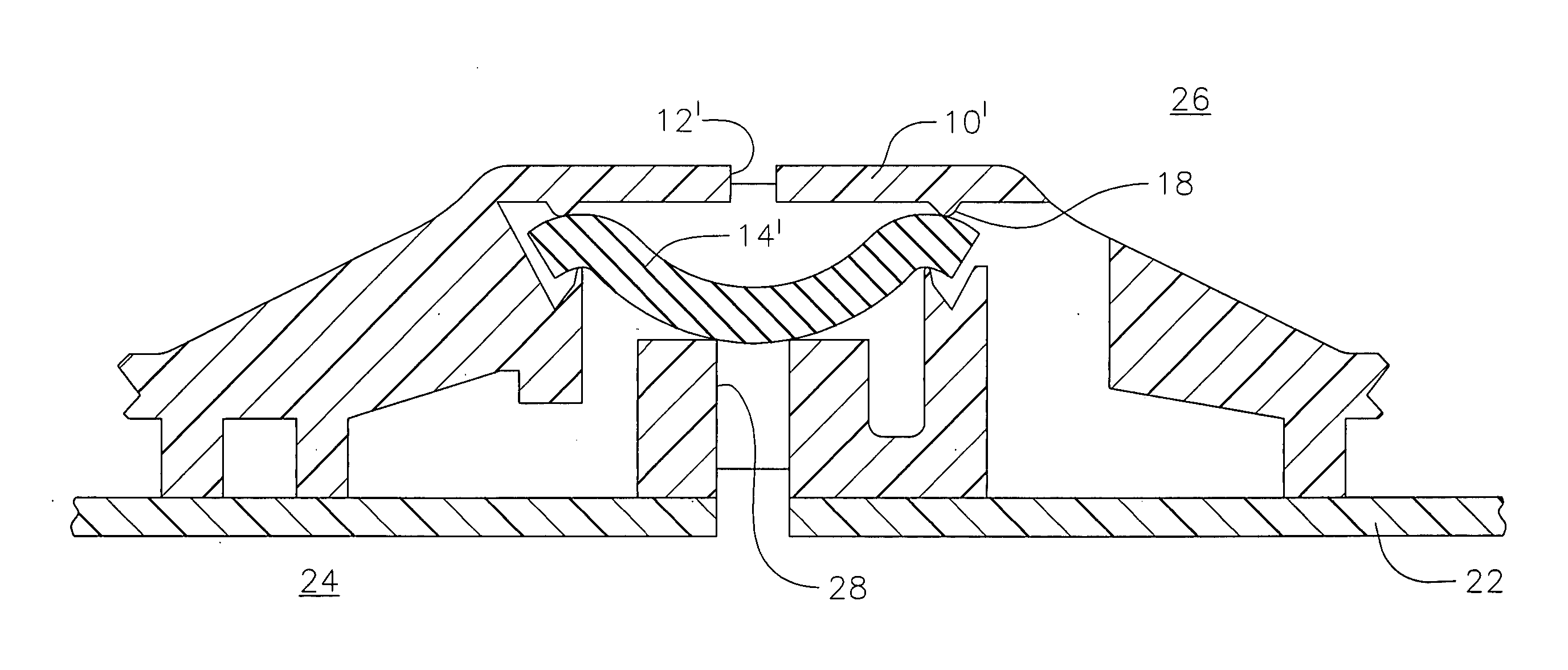
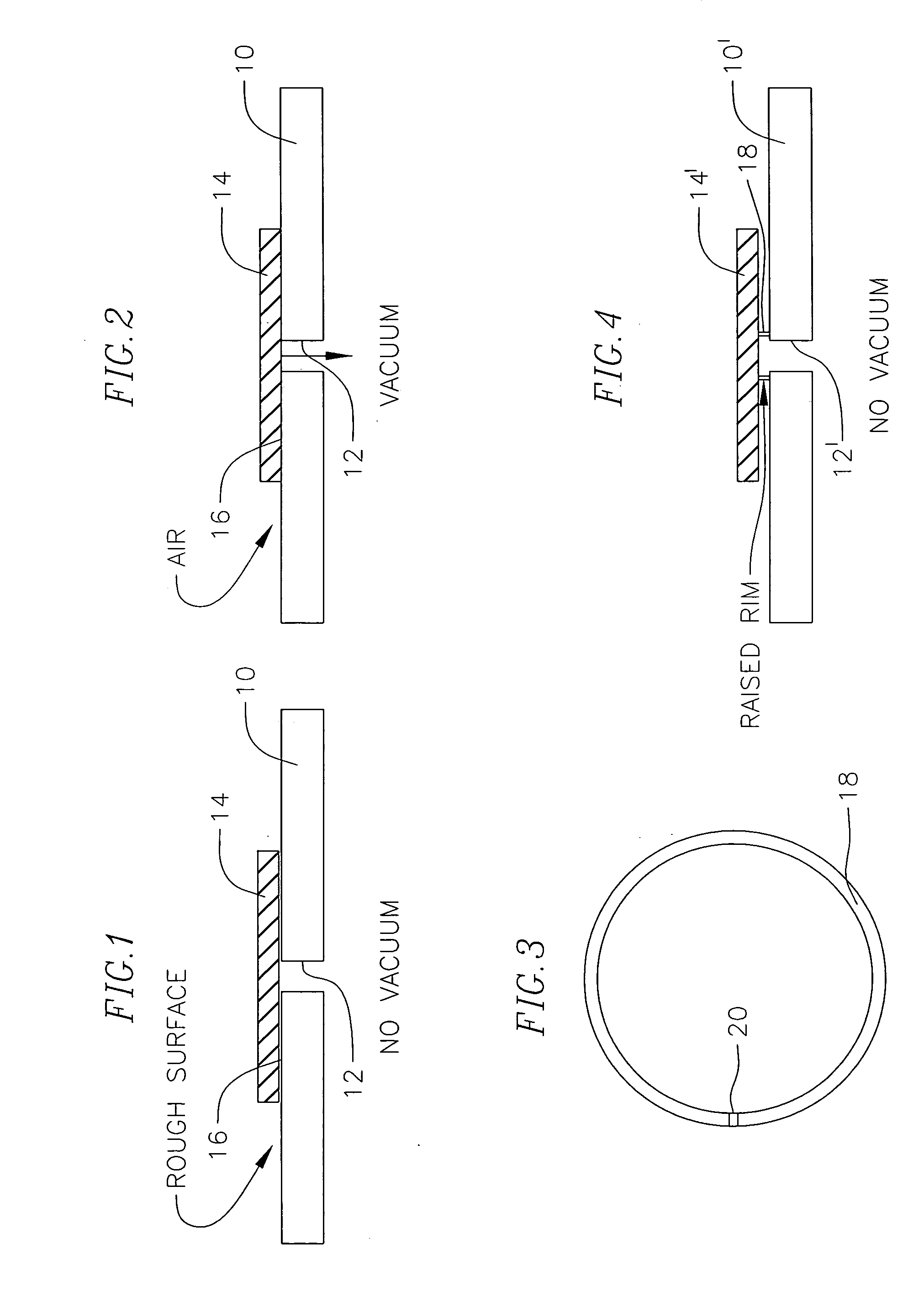
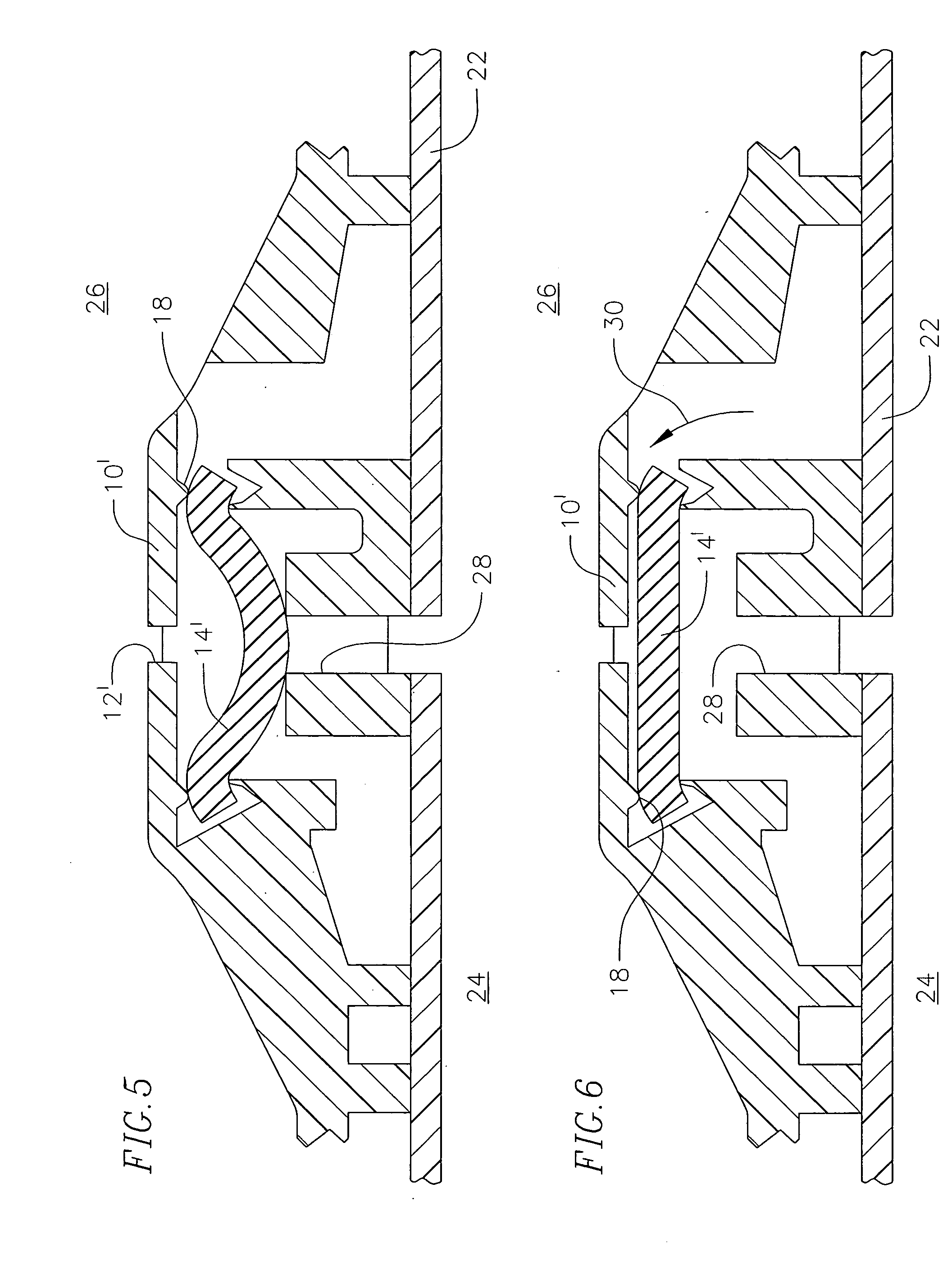
A drip irrigation emitter includes a housing containing an inlet opening for receiving water from a supply tube and an outlet opening for emitting water at a pressureless drip rate. A labyrinth inside the emitter receives water from the supply tube through the inlet opening, reducing its pressure and emitting the water at a drip rate. A flexible pressure-compensating diaphram inside the housing flexes elastically under pressure changes of water entering in the opening from the supply tube. A raised structured surface positioned between the inlet opening and the diaphram prevents the diaphram from sealing off water entry to the emitter housing through the inlet opening when water pressure in the supply tube is shut off. The raised structured surface is configured to allow air contained in the soil to be drawn backwards through the emitter at a very slow rate, thereby inhibiting emitter blockage caused by soil ingestion.

Application Domain

Climate change adaptationWatering devices +3

Technology Topic

Water entryWater pressure +3

Image

  • Anti-syphon emitter
  • Anti-syphon emitter
  • Anti-syphon emitter

Examples

  • Experimental program(1)

Example

EXAMPLE
[0022] An experimental subsurface drip irrigation (SDI) effluent disposal system according to this invention was installed, operated and monitored. The principal purpose of the trial was to quantify the environmental hydraulic performance of a high rate SDI effluent disposal application utilizing tertiary treated municipal effluent to a land disposal site comprising volcanic soils within a forest situation, which involved very severe terrain and a significantly hilly and undulating topography.
[0023] The bulk of the trial utilized standard 16 mm OD 2 L/hr PC Wasteflow, which was laid out conventionally across the contour. (Wasteflow is a product of Geoflow, Inc.) One separate and distinct portion of the project included three buried lines with the anti-syphon drip emitter of this invention (Anti-syphon emitters herein). The emitters/pipe were 18 mm OD 2 L/hr PC and did not include bactericide-lined tube. The Anti-syphon emitters included Rootguard (Rootguard is a product of Geoflow, Inc.). There were two flow meters within the trial, one recording just the Anti-syphon performance, the other the Wasteflow.
[0024] The Anti-syphon tubes were each approximately eighty meters long. These tubes were connected to-a pressure submain with a conventional layout including a VBK vacuum relief valve. There was also a VBK vacuum relief valve directly downstream of the filter (to break any dynamic vacuum) which because of the system configuration is the point of valve closure for an irrigation cycle (via a pressure sustaining valve closing on low pressure).
[0025] Each tube then RISES almost one meter over a forty meter distance to a high point, then FALLS from that high point fifteen meters over a further forty meter distance to a low point including a short flush submain. The flush submain included a 32 mm plug (which can be removed) and manual valve in order that a hose can be connected to this point and any flush material collected and/or observed.
[0026] In general, the system operated in the order of 7.5 hours per day via fifteen half hour cycles, each being separated by a corresponding half hour rest period.
[0027] The system received no maintenance from the date it commenced full operation over a period of more than eleven months.
[0028] During operation three individual drip emitters were removed from two Anti-syphon tubes (six emitters in total) at the high point, or the fifteen meter fall side of the high point, for evaluation. These emitters were tested, found to have a decline in expected performance, then run with a chlorine solution and left over night. The following day these emitters were turned on to full pressure then off to full drain, then on again three times to flush out any debris from chlorination. The drip emitters were then retested, with results being presented in Table 1: TABLE 1 Anti-syphon Drip Emitter Tests Pre Chlorine Post Chlorine Emitter (L/hr) (L/hr) 1 1.50 2.00 2 2.20 2.50 3 1.75 1.90 4 1.50 1.70 5 2.00 2.00 6 1.40 1.50 Average 1.73 1.93
[0029] Bacterial slime growth was identified to have built up on the pressure side (side facing the middle of the drip tube) of the diaphragm immediately below the modified and welded closed “gates.” Once cut open, internally the drip emitters appeared relatively clean. It was concluded that any Anti-syphon drip emitters to be used in specified wastewater disposal projects (even incorporating tertiary standard effluent) will need to include ULTRA-FRESH anti-microbial and ROOTGUARD impregnation, (both products of Geoflow, Inc.).
[0030] Six replacement Anti-syphon drip emitters were then installed in the trial system and the system operated without further maintenance.
[0031] At the end of the trial both the Wasteflow and the Anti-syphon tubes were given a high velocity scour in the order of one foot/second velocity with the flush material being collected into a 50 Liter bucket, observed, discarded and then refilled continually. A surprising and very noticeable difference existed between the bactericide-lined Wasteflow and the non-bactericide lined Anti-syphon tubes, despite the fact that the effluent source is a very visually clean (typically 13 ppm TSS, 13 ppm BOD5) UV disinfected tertiary source.
[0032] There was only in the order of 240 meters of Anti-syphon tube, with the main trial including approximately 1,500 meters of Wasteflow. The Wasteflow trial was divided into two halves for flushing purposes. The Wasteflow lines flushed black for approximately 20 seconds out of each flush submain, then were perfectly clear within ten minutes, after a proportional clearing of bacterial material over this period. The Anti-syphon ran full black for about 30 seconds, ran very dirty with black bacterial material the size of three match heads for ten minutes and still after a further five minutes fifteen minutes in total) was still heavily laden with bacterial material the size of one match head. No inorganic solid was recovered, suggesting the Anti-syphon was working. The very noticeable difference in bacterial loading was attributed to the bactericide lining working very effectively.
[0033] Once scoured both the Wasteflow and Anti-syphon tubes received a chlorine injection and were left overnight to clean.
[0034] The next day, each flush submain in turn was scoured and observed. The Wasteflow produced 20 L of bleached white heavy dead biological material, then ran very clean with occasional biological floc. The Anti-syphon tube ran chocolate dark brown for thirty seconds and then continued to produce dark floc of a heavier load than the Wasteflow for a further ten minutes. All blocks were scoured for approximately thirty minutes with the Anti-syphon never really running perfectly clear.
[0035] On the same day, and once scoured, both the Wasteflow and Anti-syphon tubes received a second chlorine injection and were left overnight to clean.
[0036] On the following day, each flush submain in turn was scoured again and observed. Each submain produced dirty material for about thirty seconds, but was flushed for about an hour during which time black biological material up to ten mm across were occasionally sloughed off (ex the MDPE main and submains. Again the Anti-syphon was noticeably the most dirty and ran full black for the first thirty seconds.
[0037] The project incorporated a new form of telemetry for data recording and downloading (via GPRS cellular) and to present the flow meter readings in either a readily legible format, or to describe the actual flow readings, in a timely manner was is not a trivial exercise. However, the literal readings (in pulses per 3 minutes) gave a relative comparison of actual performance of both the Anti-syphon and Wasteflow over the test period and are presented in Table 2: TABLE 2 Comparative Flow Meter Results (Electronic Pulses/three minutes) Date Project Status Wasteflow Anti-syphon Start date Pre-Cleaning 21 17 Ten months later 7 10 % of Original Flow Post-Cleaning 33% 59% 11 months later 21 17 % of Original Flow 100% 100%
[0038] Note that the Wasteflow has a 50 mm flow meter and the Anti-syphon a 25 mm, so there is no correlation in actual flows between the two trials. But the relative blockage over time for each trial is considered comparative.
CONCLUSIONS
[0039] (1) Even with a high quality tertiary treated effluent source, blockage via bacterial slime build-up is a potentially significant threat.
[0040] (2) From visual observations of the flush material, there is a significant advantage to having the anti-microbial lining of the Wasteflow as compared to not including this technology, in terms of internal pipe bacterial material flushed to waste during cleaning.
[0041] (3) From the visual observations of the flush material and the flow meter readings, the Anti-syphon feature appears in the first instance to mitigate blockage via particulate ingress into the emitters due to suck back on system shut down.
[0042] (4) From visual observations of cut open Anti-syphon emitters, Ultra-Fresh anti-microbial addition should be included for certain specified wastewater projects.
[0043] (5) Based upon the flow meter readings, it appears that the Anti-syphon emitters have blocked almost half as much as the standard PC emitter over time, yet both have been able to be cleaned to full original flow rate.
[0044] (6) The 18 mm PC Anti-syphon trial emitter appears to have significant technical advantages in terms of blockage resistance from both system suck back and bacterial slime build-up through operation with wastewater.

PUM

no PUM

Description & Claims & Application Information

We can also present the details of the Description, Claims and Application information to help users get a comprehensive understanding of the technical details of the patent, such as background art, summary of invention, brief description of drawings, description of embodiments, and other original content. On the other hand, users can also determine the specific scope of protection of the technology through the list of claims; as well as understand the changes in the life cycle of the technology with the presentation of the patent timeline. Login to view more.
Why Eureka
Try Eureka