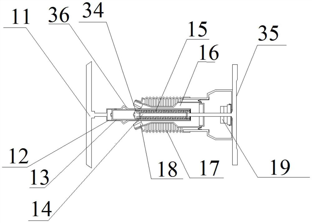
Composite load reduction device for high-speed water entry of aircraft body

A flying body and high-speed technology, applied in the field of flying body entering water, can solve problems such as damage to electronic equipment

Active Publication Date: 2021-02-26
DALIAN UNIV OF TECH
View PDF9 Cites 22 Cited by
  • Summary
  • Abstract
  • Description
  • Claims
  • Application Information

AI Technical Summary

Problems solved by technology

When an underwater vehicle or an air-launched torpedo falls from a high altitude, the head of the vehicle will be subjected to a huge short-term impact pressure at the moment it hits the water, which may cause damage to the internal structure of the vehicle, especially the electronic equipment.

Method used


Image

  • Composite load reduction device for high-speed water entry of aircraft body
  • Composite load reduction device for high-speed water entry of aircraft body
  • Composite load reduction device for high-speed water entry of aircraft body

Examples


Embodiment Construction

[0046] It should be noted that, in the case of no conflict, the embodiments of the present invention and the features in the embodiments can be combined with each other. The present invention will be described in detail below with reference to the accompanying drawings and examples.

[0047] In order to make the purpose, technical solutions and advantages of the embodiments of the present invention clearer, the technical solutions in the embodiments of the present invention will be clearly and completely described below in conjunction with the drawings in the embodiments of the present invention. Obviously, the described embodiments It is only some embodiments of the present invention, but not all embodiments. The following description of at least one exemplary embodiment is merely illustrative in nature and in no way taken as limiting the invention, its application or uses. Based on the embodiments of the present invention, all other embodiments obtained by persons of ordina...


PUM


Abstract

The invention provides a composite load reduction device for high-speed water entry of an aircraft body. The composite load reduction device comprises a fairing detachably connected to the head of a main projectile body, a cavitator and a damping device, wherein the cavitator and the damping device are arranged in the fairing; the damping device is arranged in the fairing and located between the cavitator and the main projectile body; and the damping device comprises a sealing pressure cylinder, a piston, a mounting seat, a piston rod, a tension spring, an air cavity and buffer air. The composite load reduction device is a buffer vibration reduction device which utilizes the pneumatic damping device and buffer foam for load reduction at the same time. Meanwhile, the pneumatic damping device and the buffer foam are utilized for buffering, and the composite load reduction device has higher load reduction performance.

Description

technical field [0001] The invention relates to the technical field of water entry of a vehicle, in particular to a load reduction device that adopts a combination of aerodynamic damping type load reduction and physical foam type load reduction for buffering, and in particular relates to a composite buffer load reduction device for a vehicle body entering water at high speed device. Background technique [0002] Modern underwater vehicles require more flexible launch methods to effectively avoid tracking by radar and other devices. More and more underwater vehicles are launched by air delivery. When an underwater vehicle or an air-launched torpedo falls from a high altitude, the head of the vehicle will be subjected to a huge short-term impact pressure at the moment it hits the water, which may cause damage to the internal structure of the vehicle, especially the electronic equipment. The probability of this kind of damage increases rapidly with the increase of the impact v...

Claims


Application Information

Patent Timeline
Patent Type & Authority Applications(China)
IPC IPC(8): F16F15/02F16F15/023F16F15/04F16F15/08F16B1/02B63C3/00F42B19/00
CPCF16F15/022F16F15/0232F16F15/046F16F15/085B63C3/00F42B19/00F16B1/02F16B2200/83
Inventor 李尧宗智孙铁志李海涛王世晟张宝剑
Owner DALIAN UNIV OF TECH
Why Eureka
Try Eureka