
Apparatus and process for water conditioning

a technology of apparatus and water conditioning, applied in the field of apparatus and process for water conditioning, can solve the problems of reducing heat exchanger efficiency, poor thermal conductivity, and less soluble in warm water than in cool water, and achieve the effect of reducing the amount of evaporative cooling system blowing water

Active Publication Date: 2007-01-02
OWENS SAMUEL RUPERT
View PDF20 Cites 21 Cited by
  • Summary
  • Abstract
  • Description
  • Claims
  • Application Information

AI Technical Summary

Benefits of technology

"The present invention provides a system and process for conditioning evaporative cooling water by reducing the amount of blowdown water and precipitated solids, while increasing the pH of the water. This is achieved by adding a buffer and conditioner to the water, circulating it through a reaction chamber, and removing the precipitated solids and some of the buffered water through a drain. The system also includes a corrosion inhibitor blend to prevent corrosion in the system. The process includes steps of adding a buffer to the water, adding a conditioner to the water, and removing the precipitated solids and some of the buffered water from the reaction chamber for disposal. The invention reduces the amount of chemicals used and the amount of water needed for the process."

Problems solved by technology

When a water containing calcium bicarbonate is heated, as in cooling of air conditioning systems or other equipment, the heat in the heat exchanger, will strip off one molecule of carbon dioxide, rendering the remaining calcium salt to calcium carbonate (limestone), also known as “scale.” This precipitate, the scale, is less soluble in warm water than in cool water and has very poor thermal conductivity, thus reducing heat exchanger efficiency.
Also, water with high concentrations of solids are “wasted” or “blown down” through the system drain to a sewer or ditch, and this must be replaced with makeup water as well.
Various combinations of chemicals and inorganic acids are used, but, for example, the current state-of-the-art limits a cooling system using makeup water with 150 parts per million hardness, to a concentration ratio of less than 6, when the total circulating system has a total maximum alkalinity of 600 ppm.
In addition, the relatively high concentration of sulfuric acid renders it potentially corrosive.
Sulfuric acid can also be hazardous to handle.
For example, such processes do not provide what is needed, that is an effective process for reducing the amount of blowdown water and scale formation at the heat exchanger, using relatively small amounts of chemicals.

Method used


Image

  • Apparatus and process for water conditioning
  • Apparatus and process for water conditioning
  • Apparatus and process for water conditioning

Examples


example 1

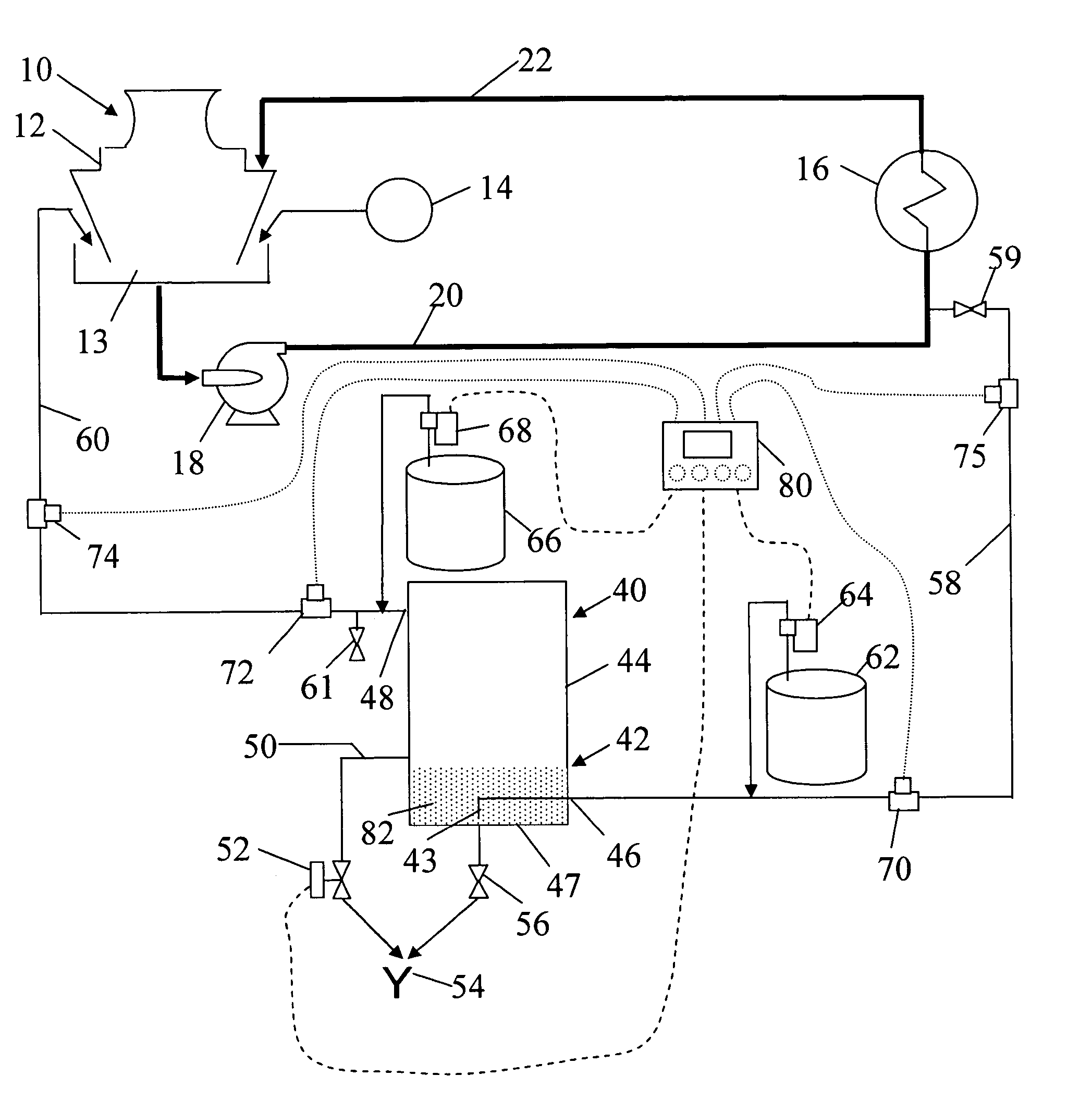
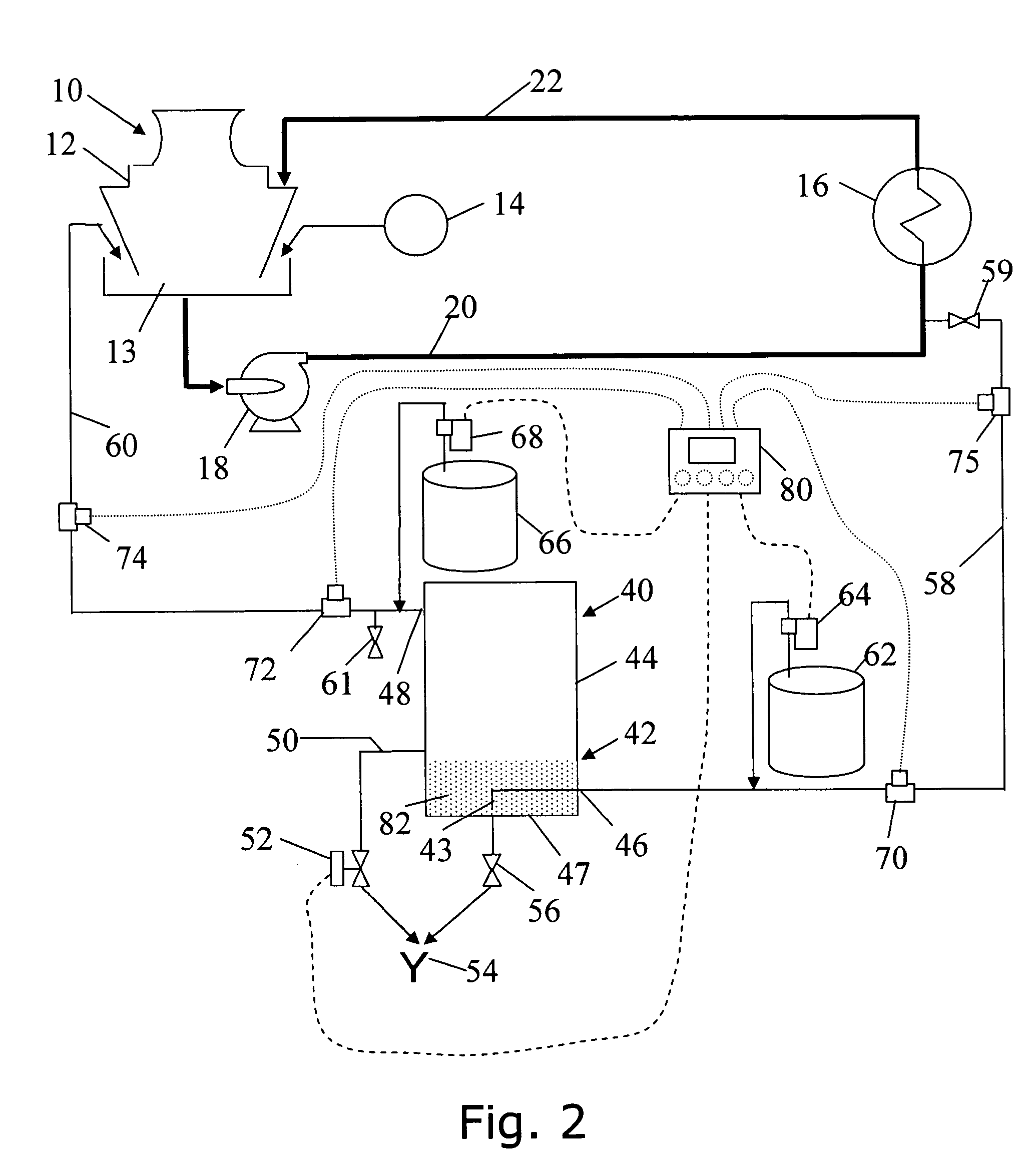
[0083]An exemplary embodiment of the apparatus and processes of the present invention is illustrated by a first example with respect to the evaporative cooling system 10 shown schematically in conjunction with an exemplary embodiment of my invention 40 in FIG. 2.

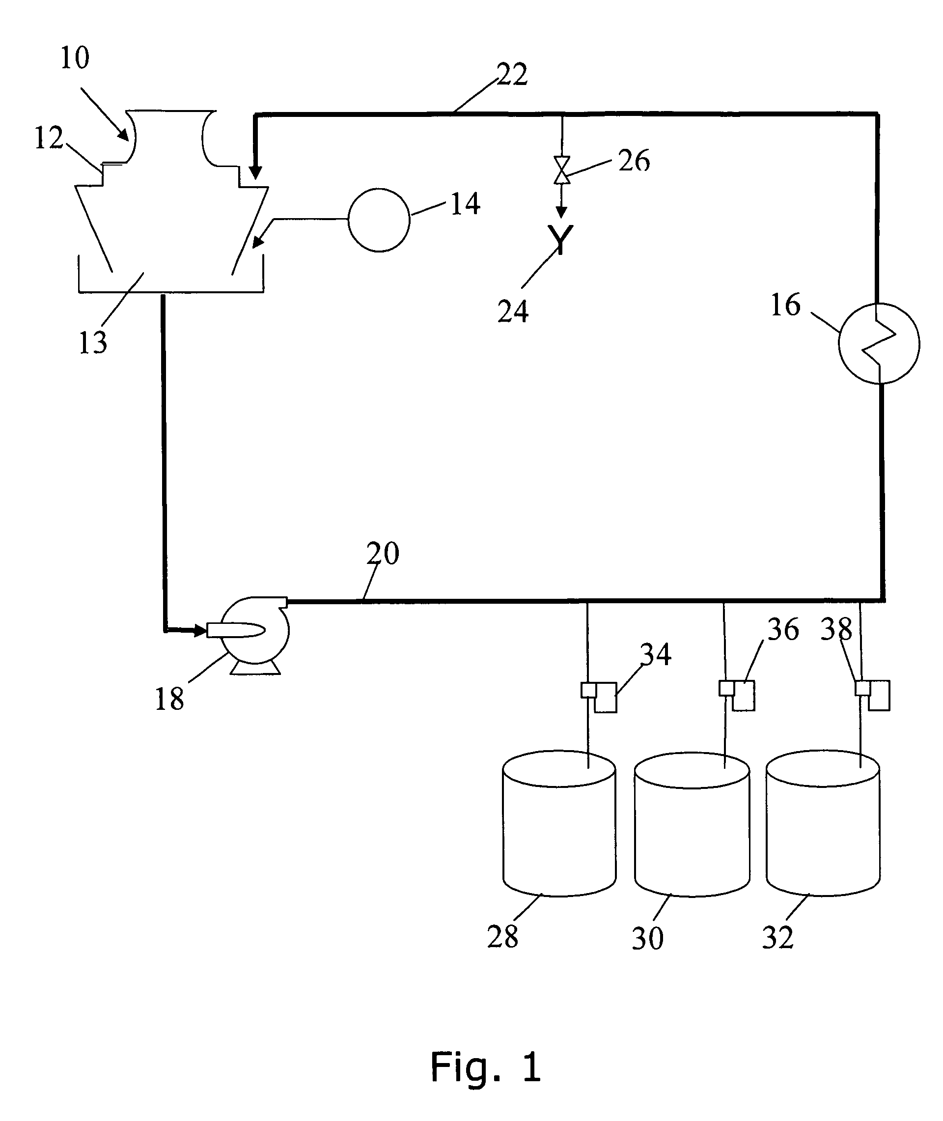
[0084]Confidential and experimental tests of this exemplary embodiment were conducted over a period of weeks on an evaporative cooling system 10 servicing a multi-story office building. Prior to the installation of my invention, the hardness of the evaporative cooling system water at a time shortly before blowdown through the drain 24 was typically about 850 ppm. Following blowdown and the addition of makeup water, the hardness was typically 765 ppm. The highest concentration ratio achieved by the owners in prior treatments was approximately 5.5, and the cooling system's blowdown volume was approximately 20 percent of the evaporation in gallons per day.

[0085]In this first example, my process was enabled using the configurati...

example 2

[0102]An exemplary embodiment of the apparatus and processes of the present invention is illustrated by a second example with respect to the evaporative cooling system 10 shown schematically in FIG. 2. In this example, the controller 80 is installed and connected as described above. The controller is microprocessor based and is configured to receive the pH value measured by the supply line pH monitor for the evaporative cooling water entering the tank, and to cause the conditioner injection pump 64 to inject conditioner from the conditioner supply 62 when the pH is shown by the pH measurement to be less than the 9.2–9.4 optimum range, or about to fall from such range. Subsequent measurements communicated to the controller, indicating the pH has returned to the pre-determined desired level, cause the controller to signal the conditioner injection pump to cease injection.

[0103]Similarly, the controller 80 in this exemplary embodiment is configured to receive the pH value measured by t...

example 3

[0107]An exemplary embodiment of the apparatus and processes of the present invention is illustrated by a third example with respect to the evaporative cooling system 10 shown schematically in FIG. 2. In this example, the glycolic acid was replaced by a 10 percent citric acid solution. The substitution worked in the process although it was noted that significantly increased volumes of citric acid and increased chemical handling were required, when compared to glycolic acid.


PUM

PropertyMeasurementUnit
reaction timeaaaaaaaaaa

Abstract

A conditioning process and equipment are provided for removing hardness from water circulated in a system, such as an evaporative cooling system. A sidestream from such system is routed to a reaction chamber and back to the system. A conditioner is added to the sidestream before entering the reaction chamber and a buffer is added to the sidestream exiting the reaction chamber. Since some of the buffered sidestream is re-circulated, a fluid bed develops in the reaction chamber consisting of conditioner, buffer, precipitated solids and sidestream water. Continued sidestream water entry mixes with the fluid bed causing additional precipitation of solids. An upper outlet on the reaction chamber regulates the height of the fluid bed, and a drain provides for periodic discharge of the lower fluid bed. In another embodiment, a corrosion inhibitor blend is pre-mixed with the buffer, resulting in a softer, more readily drainable fluid bed.

Description

CROSS-REFERENCE TO RELATED APPLICATION[0001]This application claims priority from U.S. Provisional Patent Application Ser. No. 60 / 568,134, filed May 5, 2004, and U.S. Provisional Patent Application Ser. No. 60 / 648,097 filed Jan. 28, 2005, the inventor for both applications being Samuel Rupert Owens.BACKGROUND OF THE INVENTION[0002]1. Field of the Invention[0003]The field of the invention is water treatment, or, more specifically, my invention relates to the treatment of water used in systems wherein water is circulated for repeated use, such as evaporative cooling systems.[0004]2. Description of Related Art[0005]Evaporative cooling water is used to cool various liquids or gases, in cooling systems using an evaporative cooling unit, a heat exchanger and a source of makeup water piped together in a circulating line. The heat exchanger warms the circulating water, which is circulated back to the cooling tower. The warmed water cascades down inside the cooling tower, and cools by evapor...

Claims


Application Information

Patent Timeline
Patent Type & Authority Patents(United States)
IPC IPC(8): C02F1/58C02F5/02C02F1/00C02F1/52C02F1/66C02F5/04C02F5/08C02F9/00
CPCC02F1/66C02F5/02C02F9/00C02F2103/023C02F2301/043C02F2303/08C02F2301/08
Inventor OWENS, SAMUEL RUPERT
Owner OWENS SAMUEL RUPERT
Learn More