Lighting control having a captured offset linear guide system

a linear guide and control device technology, applied in the direction of emergency power supply arrangements, electric apparatus casings/cabinets/drawers, instruments, etc., can solve the problems of reducing the lifetime of potentiometers and elongated slots in the faceplates,

Active Publication Date: 2006-11-16
LUTRON TECH CO LLC
View PDF15 Cites 15 Cited by
  • Summary
  • Abstract
  • Description
  • Claims
  • Application Information

AI Technical Summary

Benefits of technology

[0012] In a preferred embodiment of the present invention, the faceplate further comprises two guide rails and an alignment rail all parallel to the longitudinal axis of the elongated slot. The offset member is held close to the faceplate by the guide rails and i

Problems solved by technology

This can cause intermittent behavior of the potentiometer, require periodic cleaning of the slider control, and decrease the lifetime of the potentiometer.
Also, since dimmers are connected to line-voltage potentials,

Method used


Image

  • Lighting control having a captured offset linear guide system
  • Lighting control having a captured offset linear guide system
  • Lighting control having a captured offset linear guide system

Examples


Embodiment Construction

[0021] The foregoing summary, as well as the following detailed description of the preferred embodiments, is better understood when read in conjunction with the appended drawings. For the purposes of illustrating the invention, there is shown in the drawings an embodiment that is presently preferred, in which like numerals represent similar parts throughout the several views of the drawings, it being understood, however, that the invention is not limited to the specific methods and instrumentalities disclosed.

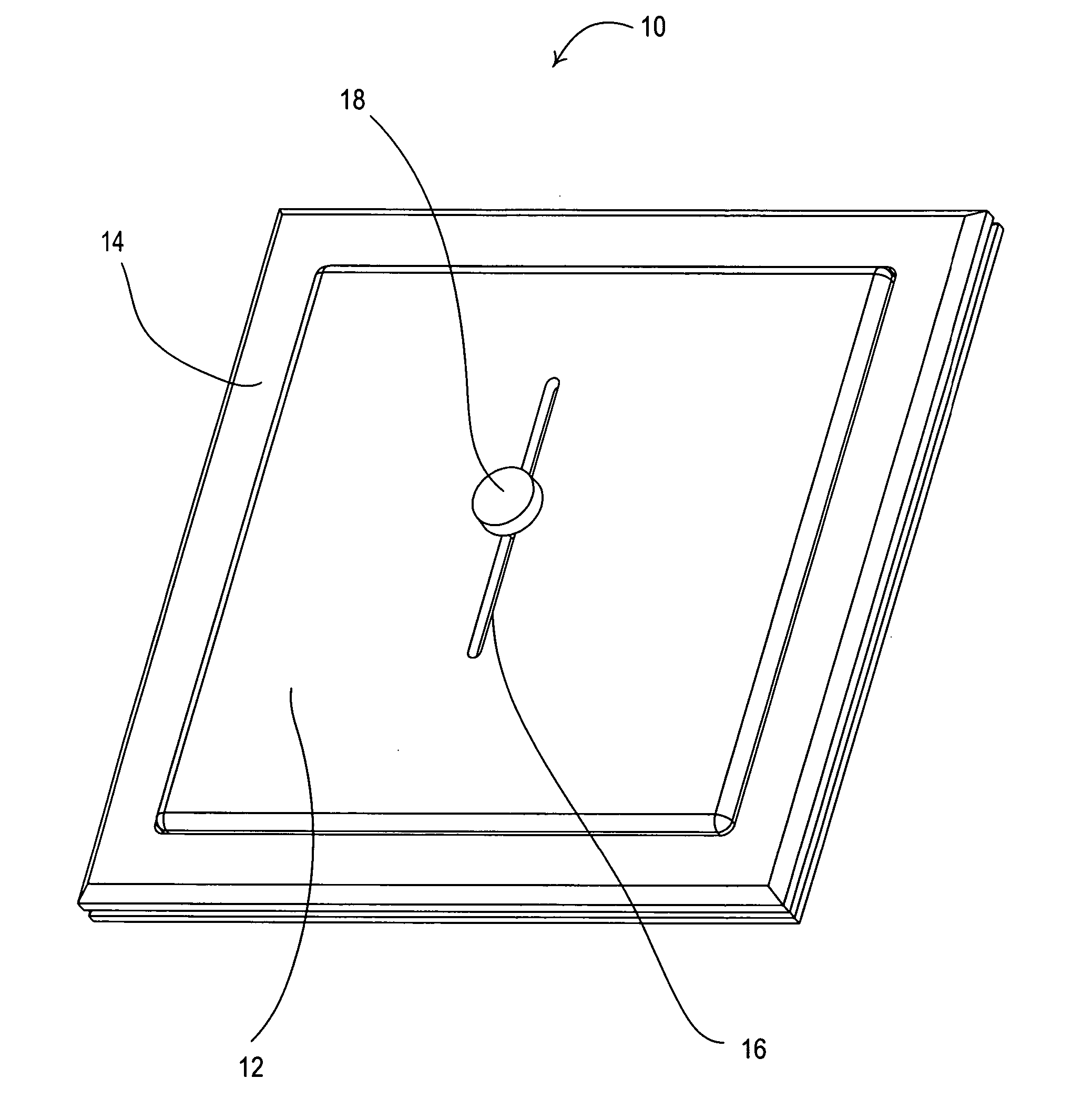
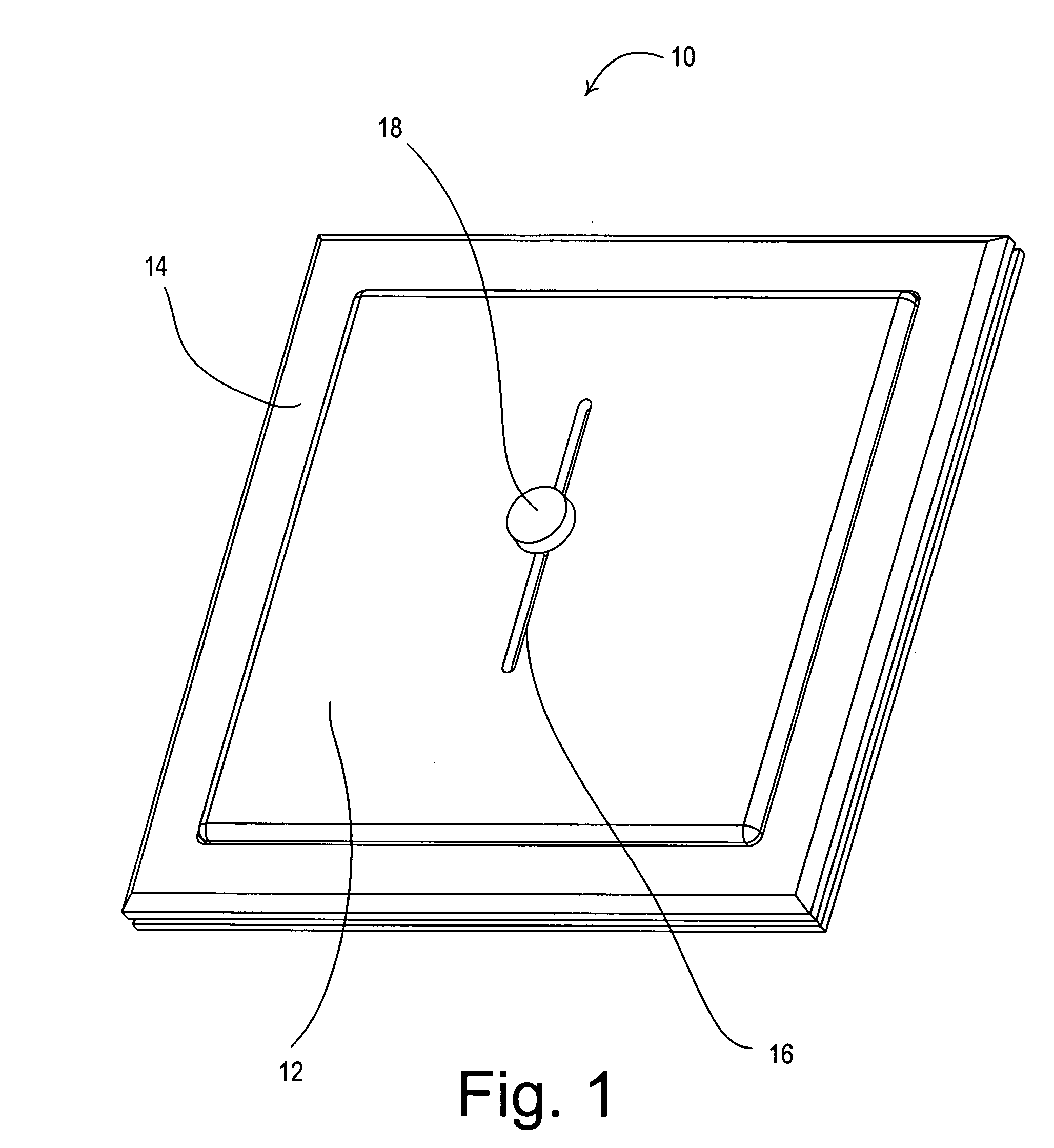
[0022]FIG. 1 shows a perspective view of a lighting control device 10 according to the present invention. A faceplate 12 of the lighting control device 10 is provided surrounded by an frame 14. The faceplate 12 includes an elongated slot 16. A knob 18 is provided for a user interface for the lighting control device. The lighting control device 10 may be a dimmer which is connected in series between an alternating-current (AC) power source and a lighting load and includes a sem...


PUM


Abstract

A captured offset linear guide system for a lighting control device includes a faceplate having an elongated slot, a knob, an offset member, and a linear potentiometer. The offset member allows the linear potentiometer to be offset from the elongated slot of the faceplate to prevent dirt and dust from collecting on the potentiometer. Also, the offset linear guide system prevents insertion of an object into the internal structure of the lighting control device where it might come into contact with energized electrical components. The faceplate includes two guide rails, which hold the offset member close to the faceplate and allow for easy assembly of the faceplate to the lighting control device. Further, the faceplate includes an alignment rail, which prevents the offset member from rotating and further constrains the offset member to move in a straight line within the slot.

Description

RELATED APPLICATIONS [0001] This application is related to commonly-assigned U.S. Provisional Application Ser. No. 60 / 680,218, filed May 12, 2005, having the same title as the present application, the entire disclosure of which is hereby incorporated by reference.BACKGROUND OF THE INVENTION [0002] 1. Field of the Invention [0003] The present invention relates to lighting control devices, specifically lighting control devices having linear sliders. [0004] 2. Description of the Related Art [0005] Many control devices incorporate linear slide mechanisms on a user interface to allow a continuous range of adjustment of a characteristic of the device being controlled. For example, many residential dimmers include linear sliders for continuous control of the intensity of a connected lamp from a minimum to a maximum value. Also, theatrical stage-boards include many sliders for modification of the intensities, colors, and other characteristics of the theatrical lights during a performance. F...

Claims


Application Information

Patent Timeline
IPC IPC(8): H02J9/02
CPCH01H3/0213H05B39/044H05B37/0209H05B47/10Y02B20/00Y10S315/04Y10S323/905
Inventor ABEL, RYAN L.
Owner LUTRON TECH CO LLC
Why Eureka
Try Eureka