

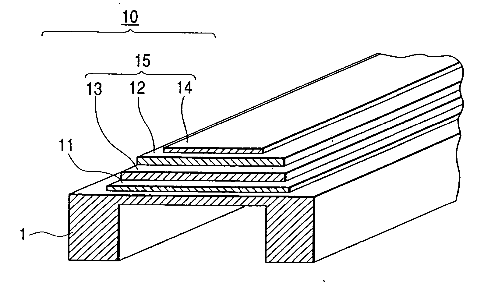
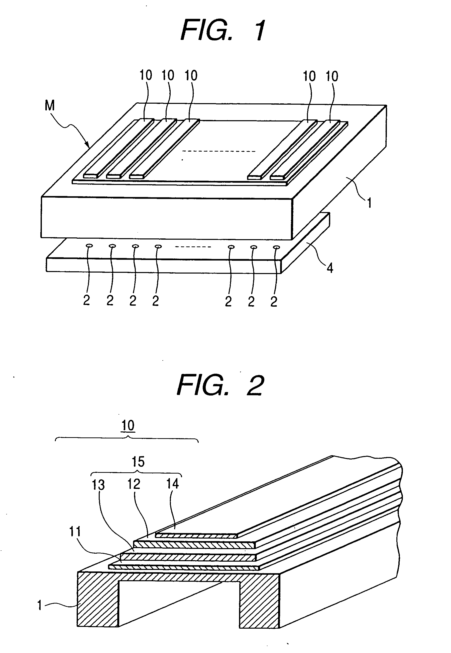
Piezoelectric element
a piezoelectric actuator and piezoelectric technology, applied in piezoelectric/electrostrictive device material selection, piezoelectric/electrostrictive/magnetostrictive device material selection, etc., can solve the problem of not having a piezoelectric element capable of avoiding an electrode peeling, and achieve excellent piezoelectric property, high reliability, and satisfactory adhesion
- Summary
- Abstract
- Description
- Claims
- Application Information
AI Technical Summary
Benefits of technology
Problems solved by technology
Method used
Image

Examples
examples 2 , 3
EXAMPLES 2, 3, COMPARATIVE EXAMPLE 2
[0103] A procedure of producing a piezoelectric element of Example 2 is as follows.
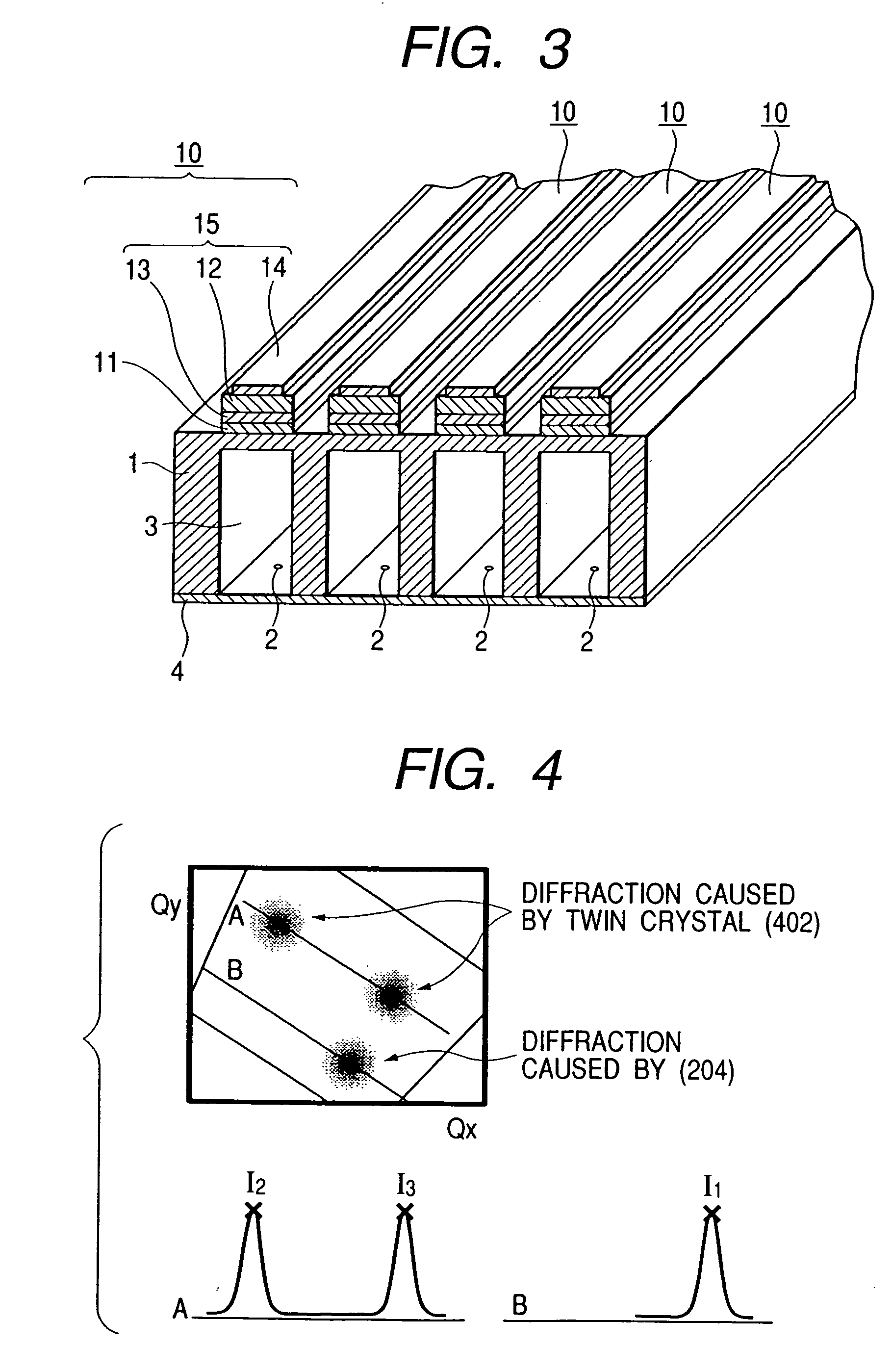
[0104] On a La-doped SrTiO3 (100) substrate serving also as a lower electrode, a piezoelectric material PZN [Pb(Zr0.55Ti0.45)O3] was prepared with a thickness of 3 μm by a MO-CVD method at a substrate temperature of 400° C. or higher, and the piezoelectric material PZT was subjected to an X-ray diffraction. A 2θ / θ measurement detected only reflection peaks resulting from (00L) planes (L=1, 2, 3, . . . , n: n being an integer). Also a positive polar point measurement of a non-symmetrical plane (204) provided reflection peaks in 4-times symmetry. As a result, it was confirmed that the piezoelectric PZT film was oriented in all the axes with an orientation rate of 100%. Also a positive polar point measurement of a symmetrical plane (004) provided a diffraction pattern as schematically shown in FIG. 5, and an inverse lattice space mapping of (204) showed a diffraction ...
PUM
| Property | Measurement | Unit |
|---|---|---|
| thickness | aaaaa | aaaaa |
| temperature | aaaaa | aaaaa |
| thickness | aaaaa | aaaaa |
Abstract
Description
Claims
Application Information