Piezoelectric substance and manufacturing method thereof, piezoelectric element and liquid discharge head using such piezoelectric element and liquid discharge apparatus

a piezoelectric element and liquid discharge technology, applied in piezoelectric/electrostrictive/magnetostrictive devices, piezoelectric/electrostriction/magnetostriction machines, printing, etc., can solve the problems of difficult to apply bulk-like single crystal material to a high accurate minute piezoelectric element, crystal members cannot be realized, and piezoelectric properties are difficult to achieve. , to achieve the effect of high piezoelectric property and high discharge performan

Inactive Publication Date: 2007-03-01
CANON KK
View PDF24 Cites 22 Cited by
  • Summary
  • Abstract
  • Description
  • Claims
  • Application Information

AI Technical Summary

Benefits of technology

[0012] An object of the present invention is to solve the above problems and to provide a piezoelectric substance having a high piezoelectric property and a method for manufacturing such a piezoelectric substance, and a piezoelectric element. Further, an object of the present invention is to provide a liquid discharge head representing a uniform and high discharge performance and capable of being subjected to minute patterning and a liquid discharge apparatus having such a liquid discharge head.
[0018] According to the present invention, a piezoelectric substance and a piezoelectric element having a high piezoelectric property. Further, by using the piezoelectric element of the present invention, a liquid discharge head presenting a uniform and high discharge performance and capable of being subjected to minute patterning and a liquid discharge apparatus having such a liquid discharge head can be obtained.

Problems solved by technology

It is difficult to apply the bulk-like single crystal material to a high accurate minute piezoelectric element.
Further, also in the single crystal piezoelectric substance thin film of relaxor group formed by the thin film method, a high piezoelectric property which can be expected from the bulk-like single crystal member could not be realized and the difference therebetween is very great.

Method used


Image

  • Piezoelectric substance and manufacturing method thereof, piezoelectric element and liquid discharge head using such piezoelectric element and liquid discharge apparatus
  • Piezoelectric substance and manufacturing method thereof, piezoelectric element and liquid discharge head using such piezoelectric element and liquid discharge apparatus
  • Piezoelectric substance and manufacturing method thereof, piezoelectric element and liquid discharge head using such piezoelectric element and liquid discharge apparatus

Examples


embodiment 1

[0117] A procedure for manufacturing a piezoelectric element of an embodiment 1 is as follows:

[0118] A substrate having a lower electrode film was obtained by film-forming an SrRuO3(SRO) film of 200 nm on an SiTiO3{100} substrate at a substrate temperature of 600° C. by a sputtering method.

[0119] Then, lead magnesiumate niobate titanate of a piezoelectric substance was film-formed on the substrate by using a pulse MOCVD method for supplying a raw material intermittently. The film-forming method will be fully explained later. As starting raw materials, the following materials were used: [0120] (a) bis(hexa-methyl-acetyl-acetonate)lead (Pb(thd)2) [0121] (b) bis[6-ethyl-2,2-dimethyl-3,5-decane-dionate]magnesium (Mg [6-C2H5-2,2-(CH3)2-C10H15O2]2) [0122] (c) propyl-tetra-ethyl-niobium (NbC3H7(C2H5)4) [0123] (d) tetra-isopropoxy-titanium (Ti (C3H7O4)4).

[0124] First of all, the starting raw materials were heated, and mixed gases of the starting raw materials and nitrogen gas used as ine...

embodiment 2

[0128] A procedure for manufacturing a piezoelectric element of an embodiment 2 is as follows.

[0129] A substrate having a lower electrode film was obtained by film-forming an SrRuO3(SRO) film of 200 nm on an SiTiO3{100} substrate at a substrate temperature of 600° C. by a sputtering method.

[0130] Then, lead magnesiumate niobate titanate of a piezoelectric substance was film-formed on the substrate to have a film thickness of 2.2 μm by using a pulse MOCVD method similar to the embodiment 1. Mole ratios of the respective raw material gases in a supply path for mixed gas of inert carrier gas / starting raw material were adjusted so that an element ratio {Mg / (Mg+Nb)} of Mg, Nb and Ti of the raw material gas became 0.33 and an element ratio {Ti / (Mg+Nb+Ti)} became 0.27. Regarding oxygen raw material, such a material was excessively supplied to the film composition after the film formation.

[0131] The element ratios of the lead magnesiumate niobate titanate of the piezoelectric substance w...

embodiment 3

[0132] A procedure for manufacturing a piezoelectric element of an embodiment 3 is as follows.

[0133] After a TiO2 film having a thickness of 4 nm was film-formed on an Si{100} substrate on which an SiO2 layer, having a thickness of 100 nm, of a heat oxidation film was formed, a Pt film having a thickness of 100 nm was film-formed by a sputtering method at a substrate temperature of 200° C. The Pt film was a orientation film. Further, as a lower electrode film, a LaNiO3 (LRO) film having a thickness of 100 nm was film-formed on the Pt film by the sputtering method at the substrate temperature of 300° C. Further, an SrRuO3 (SRO) film having a thickness of 200 nm was film-formed on the LNO layer at the substrate temperature of 600° C., thereby obtaining a substrate including the lower electrode film and the like. Both the electrode film and the SRO film were orientation uniaxial crystal films.

[0134] Then, lead magnesiumate niobate titanate of a piezoelectric substance was film-form...


PUM


Abstract

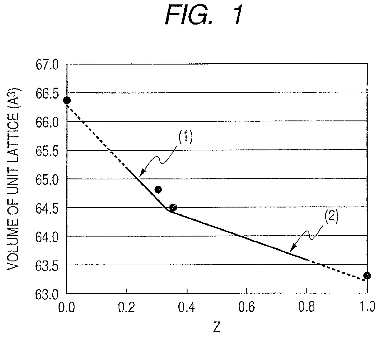
The present invention provides a piezoelectric substance of single crystal or uniaxial crystal type in which three lattice lengths a, b and c of a unit lattice of the piezoelectric substance are smaller than lattice length a0, b0 and c0 of a unit lattice of a bulk state of single crystal having the same temperature and same composition, respectively, and a volume of the unit lattice of the piezoelectric substance is smaller than a volume of the unit lattice of the bulk state of single crystal having the same temperature and same composition.

Description

BACKGROUND OF THE INVENTION [0001] 1. Field of the Invention [0002] The present invention relates to a piezoelectric substance and a manufacturing method thereof, a piezoelectric substance and a liquid discharge head using such a piezoelectric element, and a liquid discharge apparatus. [0003] 2. Description of the Related Art [0004] In recent years, piezoelectric actuators have been watched as new motors in place of electromagnetic motors in a portable information equipment field and chemical and medical field, in the point that motors can be miniaturized and be arranged with high density. During the operation, the piezoelectric actuator does not generate electromagnetic noise and is not influenced by noise. Further, the piezoelectric actuator has been watched as a technique for manufacturing equipment of sub-millimeter class as represented by a micro machine, and a minute piezoelectric element has been requested as a drive source of the equipment. [0005] In general, the piezoelectr...

Claims


Application Information

Patent Timeline
Patent Type & Authority Applications(United States)
IPC IPC(8): H01L41/187
CPCB41J2/14233B41J2/161B41J2/1623B41J2/1628B41J2/1629B41J2/1631H01L41/0973B41J2/1634B41J2/1642B41J2/1646H01L41/187H01L41/316B41J2/1632H10N30/2047H10N30/853H10N30/076
Inventor IFUKU, TOSHIHIROAOKI, KATSUMIMATSUDA, TAKANORIFUNAKUBO, HIROSHIYOKOYAMA, SHINTAROOKAMOTO, SATOSHI
Owner CANON KK
Why Eureka
Try Eureka