Backlight unit and liquid crystal display employing the same

a backlight unit and liquid crystal display technology, applied in the direction of illuminated signs, display means, instruments, etc., can solve the problems of ccfl having a comparatively short lifetime and a low color reproducibility, ccfl is much more disadvantageous in instant lighting, and ccfl is comparatively short lifetime and color reproducibility. to achieve the effect of eliminating the motion blur phenomenon

Active Publication Date: 2006-11-16
SAMSUNG ELECTRONICS CO LTD
View PDF6 Cites 17 Cited by
  • Summary
  • Abstract
  • Description
  • Claims
  • Application Information

AI Technical Summary

Benefits of technology

[0013] The present invention provides a backlight unit that can effectively remove the motion blur phenomenon by eliminating light interference between division areas of the backlight unit in a selected area where it is desired to display an image when a light source is lighted in synchronization with a scanning time of a liquid crystal panel, and an LCD employing the backlight unit.

Problems solved by technology

However, the CCFL has a comparatively short lifetime and a low color reproducibility.
The CCFL is much more disadvantageous with respect to lifetime and color reproducibility than a light emitting diode (LED) and is also more disadvantageous in instant lighting than an LED.
Since the CCFL is poor at instant lighting, it is difficult to employ a backlight unit using the CCFL as a light source in a time-division LCD.
However, in a case where light diverging from a selected one of the divided lighting areas invades an adjacent lighting area through the diffusion plate, when one picture is changed to another one, it is difficult to effectively remove the motion blur phenomenon such that an after-image remains.

Method used


Image

  • Backlight unit and liquid crystal display employing the same
  • Backlight unit and liquid crystal display employing the same
  • Backlight unit and liquid crystal display employing the same

Examples


Embodiment Construction

[0030] The present invention will now be described more fully with reference to the accompanying drawings, in which exemplary embodiments of the invention are shown.

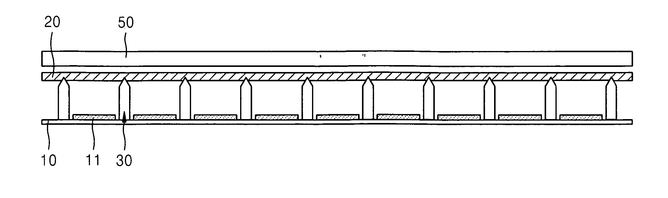
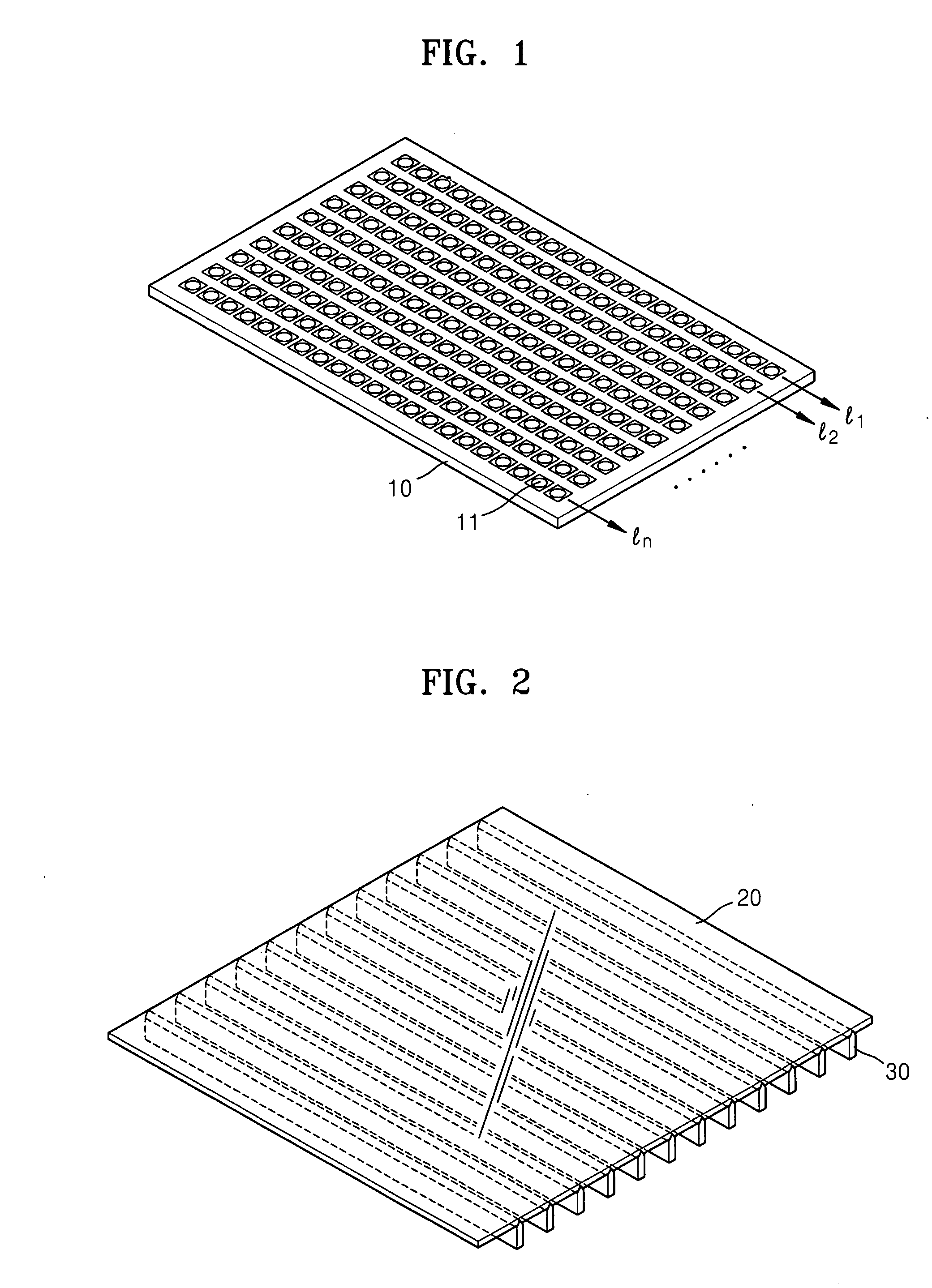
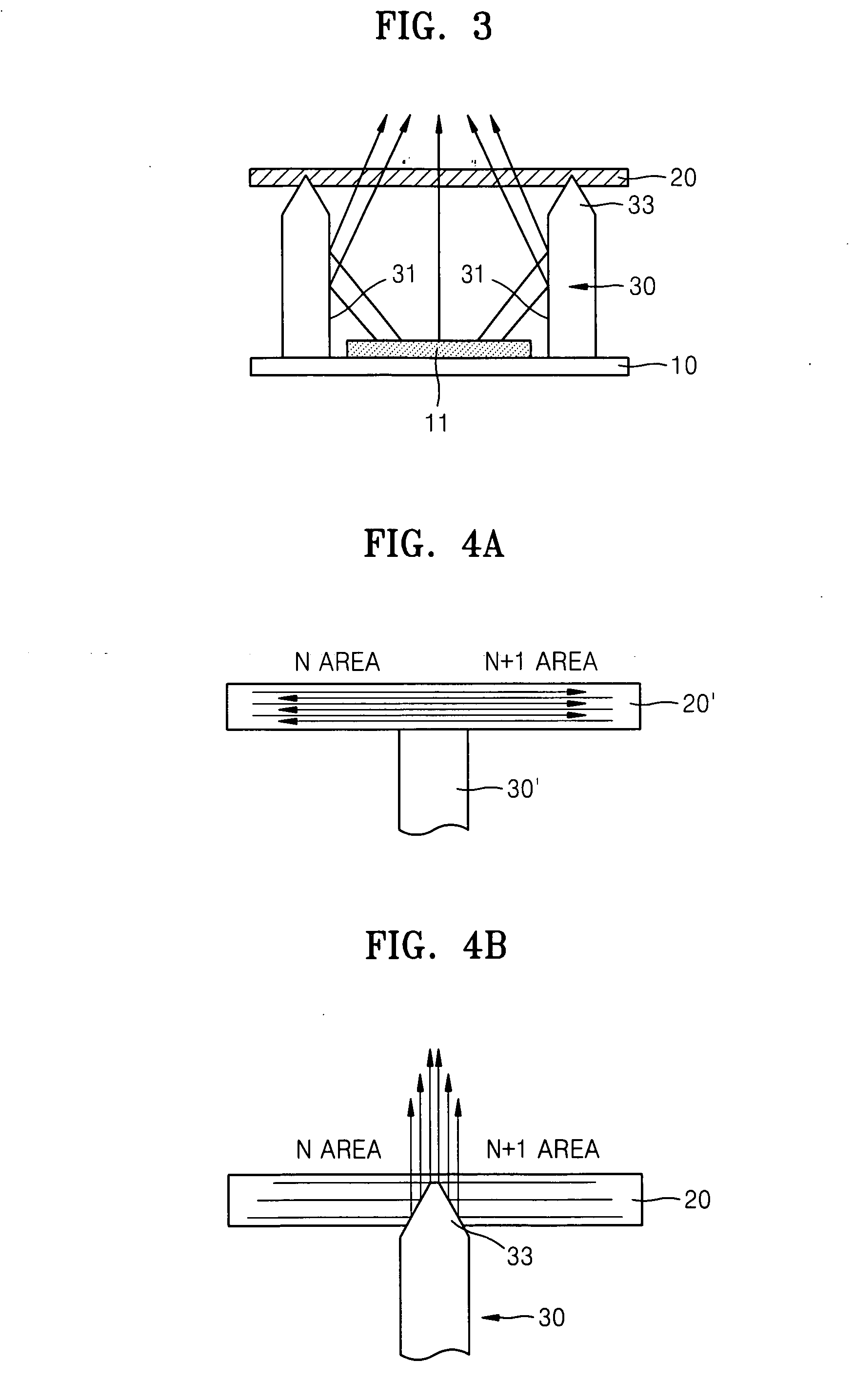
[0031]FIG. 1 is a perspective view of a base substrate of a direct light type backlight unit according to the present invention, FIG. 2 is a perspective view of a diffusion plate of a direct light type backlight unit according to the present invention, and FIG. 3 is a side view of a single division area of a direct light type backlight unit according to the present invention.

[0032] Referring to FIGS. 1 and 2, the direct light type backlight unit according to the present invention includes: a base substrate 10; a plurality of point light sources 11 arranged in two or more lines on the base substrate 10; a diffusion plate 20 disposed on the plurality of point light sources 11 to diffuse and transmit incident light such that uniform light is outputted; and one or more barrier ribs 30 between the base substrate 10 and the ...


PUM

PropertyMeasurementUnit
screen scanning timeaaaaaaaaaa
color reproducibilityaaaaaaaaaa
scan timeaaaaaaaaaa

Abstract

A backlight unit and an LCD employing the backlight unit are provided. The backlight unit includes: a base substrate; a plurality of point light sources arranged in two or more lines on the base substrate; a diffusion plate disposed over the plurality of point light sources to diffuse and transmit incident light; and at least one barrier rib forming two or more division areas by being disposed between the base substrate and the diffusion plate to be upright with respect to the base substrate between the lines and having a wall surface reflecting light incident from the plurality of point light sources, at least a portion of an end portion of the barrier rib being inserted into the diffusion plate.

Description

CROSS-REFERENCE TO RELATED PATENT APPLICATION [0001] This application claims priority from Korean Patent Application No. 10-2005-0039002, filed on May 10, 2005, in the Korean Intellectual Property Office, the disclosure of which is incorporated herein in its entirety by reference. BACKGROUND OF THE INVENTION [0002] 1. Field of the Invention [0003] The present invention relates to a backlight unit and a liquid crystal display employing the same and, more particularly, to a direct light type backlight unit having a sequential division lighting structure of division areas, and a liquid crystal display employing the same. [0004] 2. Description of the Related Art [0005] A liquid crystal display (LCD), which is a type of flat panel display, is a light receiving type display that is not self-luminescent but forms an image using incident light from an outside source. A backlight unit is disposed at a rear of the LCD to irradiate light toward a liquid crystal panel. [0006] A cold cathode flu...

Claims


Application Information

Patent Timeline
Patent Type & Authority Applications(United States)
IPC IPC(8): G02F1/133
CPCG02F1/133603G02F1/133607G02F1/1335
Inventor SEONG, KI-BUMCHO, TAE-HEEWANG, JONG-MINOH, JIN-KYOUNGKIM, SU-GUNJUNG, IL-YONG
Owner SAMSUNG ELECTRONICS CO LTD
Why Eureka
Try Eureka