Communication path monitoring system and communication network system

a communication path and monitoring system technology, applied in the field of communication path monitoring system, can solve the problems of inability to apply techniques, inability to develop software, and inability to use gmpls switches and mpls routers

Inactive Publication Date: 2006-11-16
HITACHI LTD
View PDF7 Cites 51 Cited by
  • Summary
  • Abstract
  • Description
  • Claims
  • Application Information

AI Technical Summary

Benefits of technology

[0018] This invention obtains a list of communication paths and the operational state and route of a communication path solely from information that is not dependent on the type of MPLS router or GMPLS s...

Problems solved by technology

In practice, however, GMPLS switches and MPLS routers do not always have the two because of development cost or other limitations.
Then this technique cannot be applied.
The monitoring manager has to develop, for each and every type of GMPLS switch or MPLS router it manages, software to even out the format...

Method used


Image

  • Communication path monitoring system and communication network system
  • Communication path monitoring system and communication network system
  • Communication path monitoring system and communication network system

Examples


first embodiment

[0068] A first embodiment of this invention will be described below.

[0069] Described in the first embodiment is a case where GMPLS extended RSVP-TE is employed as a signaling protocol and GMPLS extended OSPF-TE is employed as a link state routing protocol. However, this embodiment is applicable in a similar manner to other protocols such as IS-IS (“OSI IS-IS Intra-domain Routing Protocol”, IETF RFC 1142) and GMPLS CR-LDP (IETF RFC 3472, “Generalized Multi-Protocol Label Switching (GMPLS) Signaling Constraint-based Routed Label Distribution Protocol (CR-LDP) Extensions”).

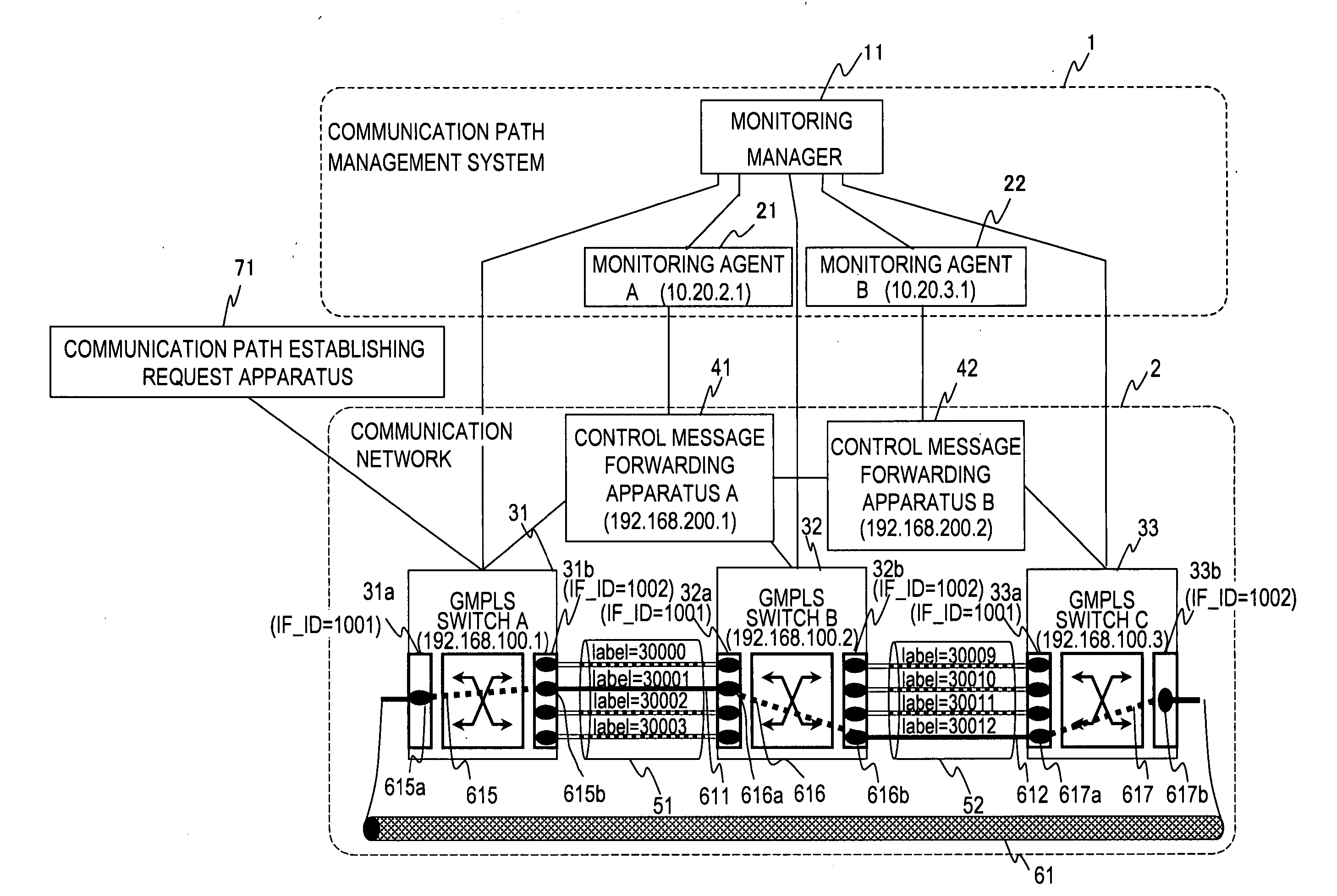
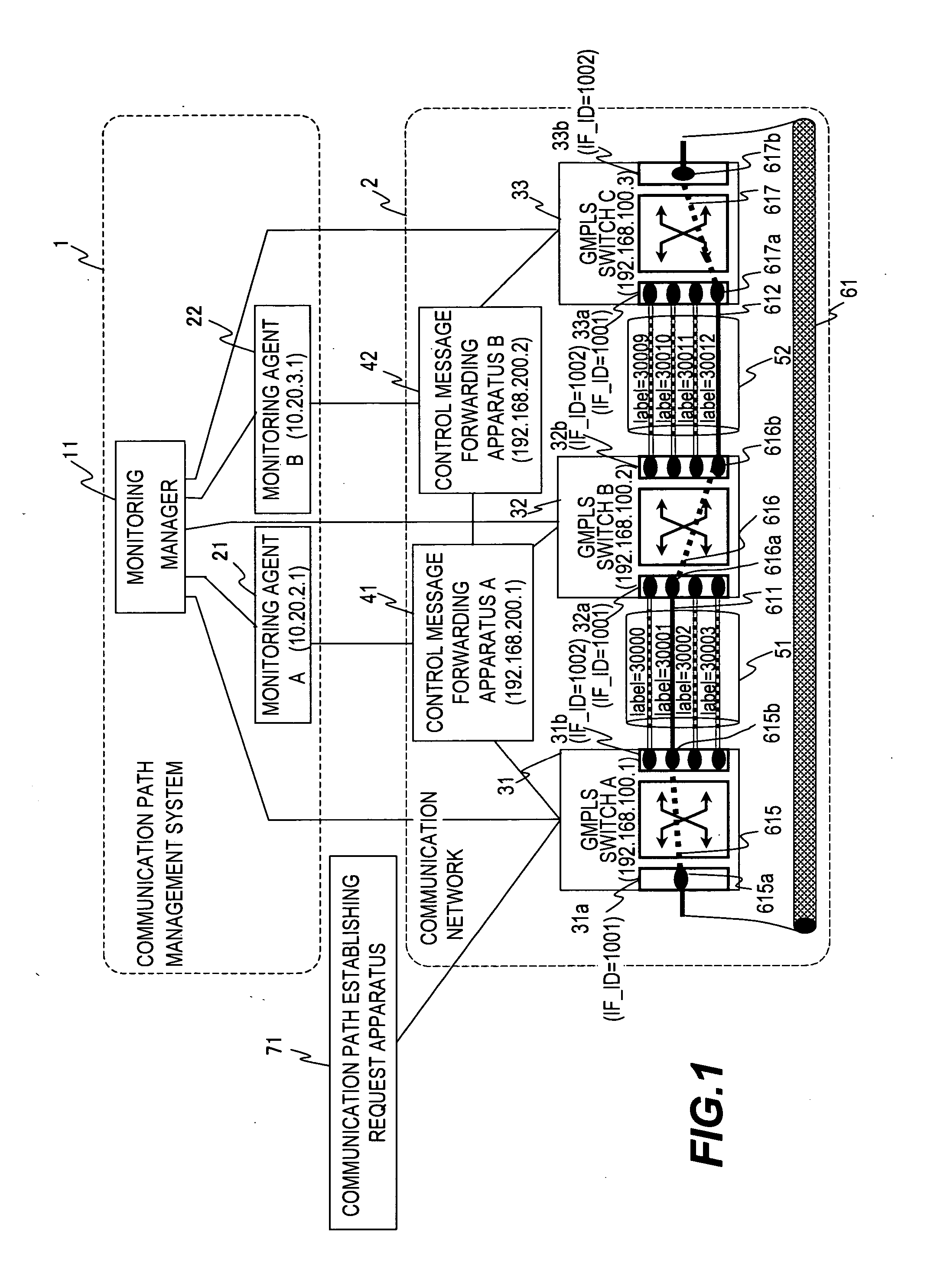
[0070]FIG. 1 is a block diagram of a network system according to the first embodiment of this invention.

[0071] The network system of the first embodiment is a GMPLS network in which GMPLS extended RSVP-TE and GMPLS extended OSPF-TE messages are exchanged over a link that is not a to-be-established communication path 61.

[0072] A communication path management system 1 of the first embodiment is composed of a monito...

second embodiment

[0297] A second embodiment of this invention will be described below.

[0298] The second embodiment will be explained as to a case of employing GMPLS extended RSVP-TE or MPLS RSVP-TE (IETF RFC 3209, “RSVP-TE: Extensions to RSVP for LSP Tunnels”) as a signaling protocol and GMPLS extended OSPF-TE or MPLS OSPF-TE as a link state routing protocol. However, this embodiment is applicable in a similar manner to other protocols such as IS-IS and GMPLS extended CR-LDP.

[0299]FIG. 20 is a block diagram of a network system according to the second embodiment of this invention.

[0300] The network system of the second embodiment is a communication network controlled by MPLS. Alternatively, the network system of this embodiment may be a GMPLS network in which a signaling protocol and a link state routing protocol are exchanged over the same links 55 and 56 as a communication path 65 to be established.

[0301] In MPLS, a signaling protocol and a routing protocol are always sent and received over the...

third embodiment

[0304] A third embodiment of this invention will be described below.

[0305] The third embodiment will be explained as to a case of employing GMPLS extended RSVP-TE as a signaling protocol and GMPLS extended OSPF-TE as a link state routing protocol. However, this embodiment is applicable in a similar manner to other cases employing protocols such as IS-IS and GMPLS extended CR-LDP.

[0306]FIG. 21 is a block diagram of a network system according to the third embodiment of this invention.

[0307] The network system of the third embodiment is, as in the first embodiment, a GMPLS network in which GMPLS extended RSVP-TE and GMPLS extended OSPF-TE messages are sent and received over links different from the communication path 61 to be established. While the monitoring agents A 21 and B 22 obtain messages from the control message forwarding apparatus A 41 and B 42 in the first embodiment, monitoring agents A 27, B 28 and C 29 of the third embodiment directly copy messages on links between GMP...


PUM


Abstract

Information that is not dependent on how a GMPLS switch or an MPLS router is set up (information independent of the type of GMPLS switch or MPLS router) is used to obtain attribute values of communication paths and manage communication path configurations in a communication network. Provided is a communication path management system for managing a communication network system in which a communication path is established by transferring communication path establishment control information between data switching apparatuses, including: an information collecting module which collects the communication path establishment control information; an information accumulating module which accumulates the communication path establishment control information collected by the information collecting module; and an information searching module which searches the communication path establishment control information accumulated by the information accumulating module, wherein which communication path is established is derived from the communication path establishment control information searched by the information searching module.

Description

CROSS-REFERENCE TO RELATED APPLICATIONS [0001] This application is a continuation-in-part of earlier U.S. patent Ser. No. 11 / 175,144, filed on Jul. 7, 2005 based on Japanese Patent Application P2004-317740 filed on Nov. 1, 2004, the disclosure of which is incorporated in its entirety herein by reference.CLAIM OF PRIORITY [0002] The present application claims priority from Japanese patent applications P2005-312483 filed on Oct. 27, 2005 and P2004-317740 filed on Nov. 1, 2004, the contents of which are hereby incorporated by reference into this application. BACKGROUND OF THE INVENTION [0003] This invention relates to a communication path monitoring system for a communication network that uses a link state routing protocol to determine the route of a communication path to be established and that uses a signaling protocol to establish the communication path, as well as to a communication network system composed of the communication network and the communication path monitoring system. [...

Claims


Application Information

Patent Timeline
IPC IPC(8): H04J1/16H04J3/14H04L12/70H04M3/00
CPCH04L43/0811H04L45/02H04L45/50H04L45/28H04L45/22H04L45/03
Inventor KUSAMA, KAZUHIROMAEDA, SHUJI
Owner HITACHI LTD
Why Eureka
Try Eureka