Packet and optical routing equipment and method

a technology of optical routing and equipment, applied in the field of optical communication systems, can solve the problems of complex and expensive network configurations that do not facilitate, document however does not disclose in detail the architecture of the nodes of the network, and in particular, the complexity of the architecture, so as to save the expenditure of implementation and operation.

Inactive Publication Date: 2006-11-16
TELECOM ITALIA SPA +1
View PDF5 Cites 33 Cited by
  • Summary
  • Abstract
  • Description
  • Claims
  • Application Information

AI Technical Summary

Benefits of technology

[0008] The aim of the invention is thus to provide a packet and optical routing equipment and method that are simple and offer savings in the expenditure as regards implementation and operation.
[0009] Applicant has developed a simple architecture in which both packet and non-packet signals are forwarded and routed in the same node, with an integrated control of the different parts managing the packet and non-packet signals. The presence of non-packet interfaces, not requiring packet elaboration, as well as packet interfaces, both connected to a WDM interface unit by a switching unit, allows a smooth evolution from a network based on traditional TDM (Time Division Multiplexing) circuits to a network based on more modern IP / MPLS and / or GMPLS (Generalized Multi-Protocol Label Switching) services.
[0010] In particular, the reconfigurability of the electric switching unit allows a variable proportion of input / outputs for packet and non packet signals to be connected each time to the WDM interface unit. The ratio of connected non-packet input / outputs to connected packet input / outputs is thus variable according to the need, offering a great deal of flexibility and cost saving due to the fact that in general is possible to reduce the number of lasers equipped in the WDM interfaces.

Problems solved by technology

Currently, IP / MPLS routers and non-IP equipment are attached to networks using WDM (Wavelength Division Multiplexing) systems through optical interfaces and the control of the different systems is not integrated.
This leads to complex and expensive network configurations that do not facilitate the introduction of new services in communication network.
This document however does not disclose in detail the architecture of the nodes of the network and in particular how IP and non-IP signals are multiplexed in the nodes.
Applicant remarks that this architecture is complex and involves a substantial processing of both the OTM signals from the optical backbone transmission lines and the arbitrary signals that are directly inputted in the IP packet transmission equipment.

Method used


Image

  • Packet and optical routing equipment and method
  • Packet and optical routing equipment and method
  • Packet and optical routing equipment and method

Examples


Embodiment Construction

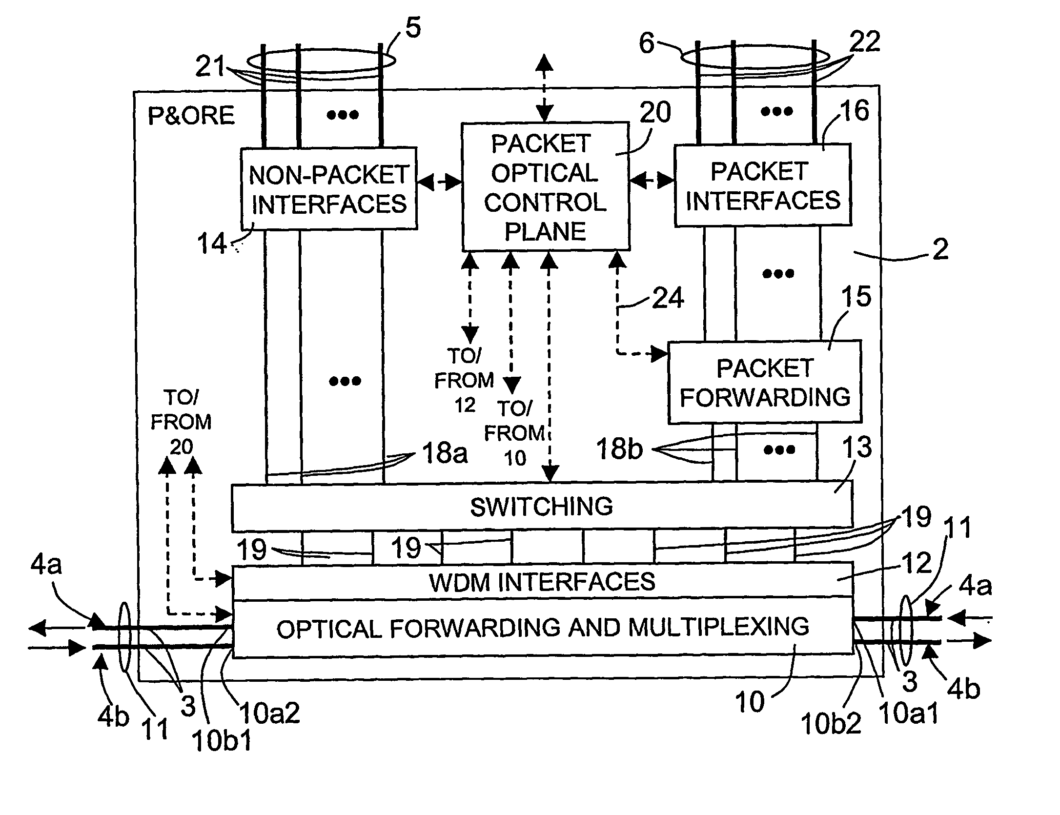
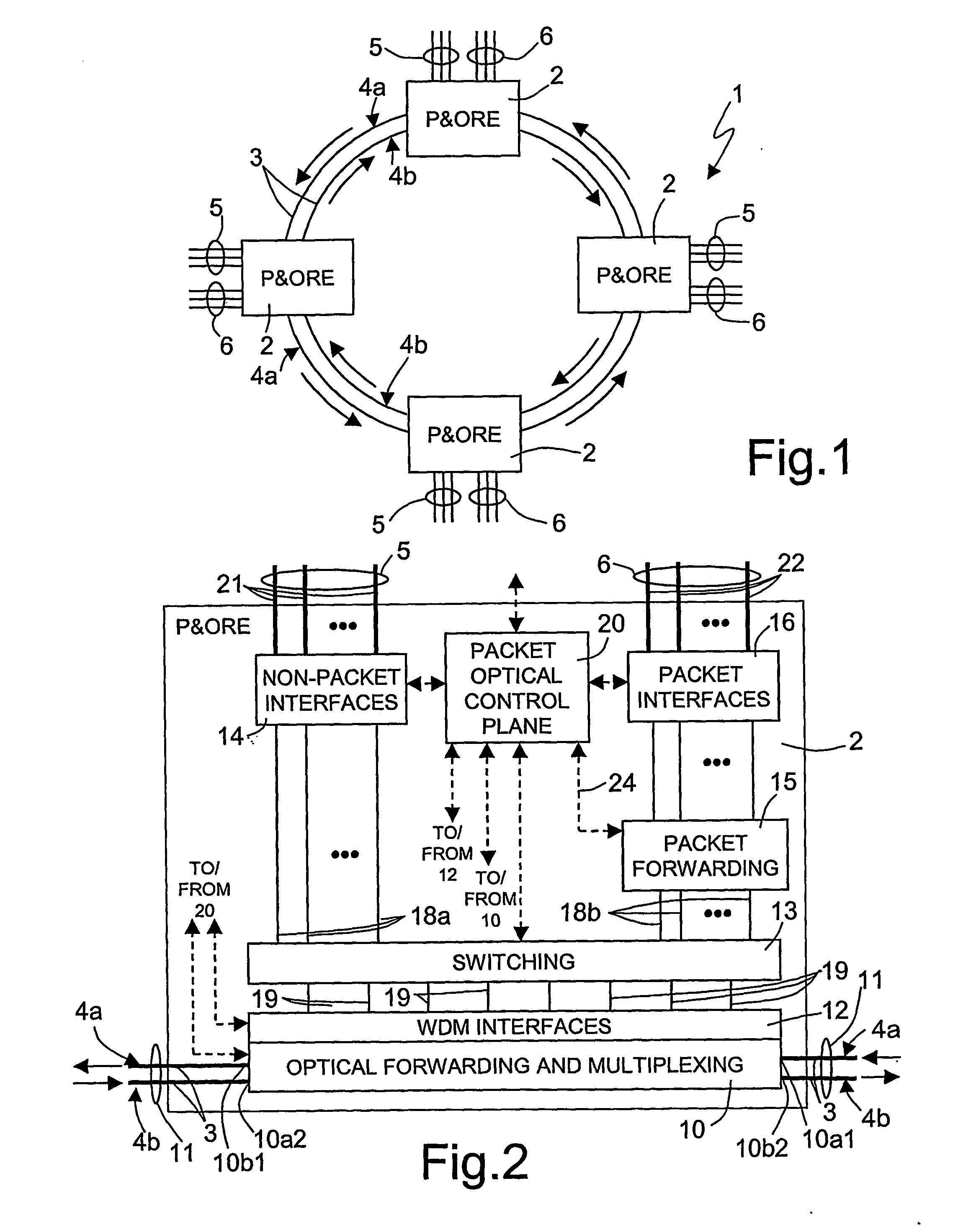
[0033]FIG. 1 illustrates an optical network 1 implementing a wavelength division multiplexing (WDM) technique and having a ring-like configuration. The ring-like configuration is only an example, and the invention is applicable to also meshed-type networks, as will be clear later on.

[0034] According to FIG. 1, the optical network 1 comprises a number of nodes 2, here four, each defining a packet and optical routing equipment (P&ORE). Each node 2 is connected to a neighboring node 2 through optical fibers 3, each optical fiber 3 being able to carry a certain number (e.g. 40) of optical wavelengths λ1, λ2, . . . , λN. The optical fibers 3 form an external ring 4a and an internal ring 4b. For example, the external ring 4a is designed to carry signals in a counter-clockwise direction and the internal ring 4b is designed to carry signals in a clockwise direction.

[0035] Each node 2 is connected to a first and a second group of interfaces 5, 6. The first group of interfaces 5 connects th...


PUM


Abstract

A packet and optical routing equipment exchanges multiplexed optical signals with other equipment in a network and exchanges branch non-packet and packet signals with client equipment. The entering branch non-packet signals are converted into electric signals by a non-packet interface and supplied directly to an electric switching unit, the entering packet branch signals are converted into electric signals, supplied to a packet forwarding module and routed to the electric switching unit. The electric switching unit switches the electric signals toward a WDM interface that converts them into optical signals at selected wavelengths that are added to the multiplexed optical signals. The entering multiplexed optical signals that should be terminated in the equipment are extracted, converted into electrical signals, and electrically switched toward the non-packet interface or the packet forwarding module according to whether they are of non-packet or of a packet type. The switching unit is of configurable type and may switch a variable ratio of electric non-packet and packet signals according to the traffic requirements.

Description

TECHNICAL FIELD [0001] The present invention relates in general to the field of optical communication systems and more in particular to a packet and optical routing equipment and method. PRIOR ART [0002] As is known, the growth of the Internet has brought to ever-increasing traffic volumes that in turn require the use of broader-band communication systems. Thus, the use of optical communication systems, employing fiber optics, has already been proposed for transmitting IP packets. The resulting increasing and progressive integration of data and voice traffic brings about the need of systems and equipment adapted to manage transmission of both traditional optical signals (e.g. SONET / SDH, Synchronous Optical Network / Synchronous Digital Hierarchy or ATM, Asynchronous Transfer Mode signals) and packet-based signals (e.g. IP / MPLS, Internet Protocol / Multi-Protocol Label Switching signals). [0003] Currently, IP / MPLS routers and non-IP equipment are attached to networks using WDM (Wavelengt...

Claims


Application Information

Patent Timeline
Patent Type & Authority Applications(United States)
IPC IPC(8): H04J14/00H04J14/02H04Q11/00
CPCH04J14/0201H04J14/0209H04J14/021H04J14/0219H04J14/0241H04J14/0283H04Q11/0062H04Q11/0066H04Q11/0071H04J14/0227
Inventor CAVAZZONI, CARLOD'ALESSANDRO, ALESSANDRO
Owner TELECOM ITALIA SPA
Why Eureka
Try Eureka