
Meter

Inactive Publication Date: 2006-11-23
SEVERN TRENT METERING SERVICES
View PDF22 Cites 2 Cited by
  • Summary
  • Abstract
  • Description
  • Claims
  • Application Information

AI Technical Summary

Benefits of technology

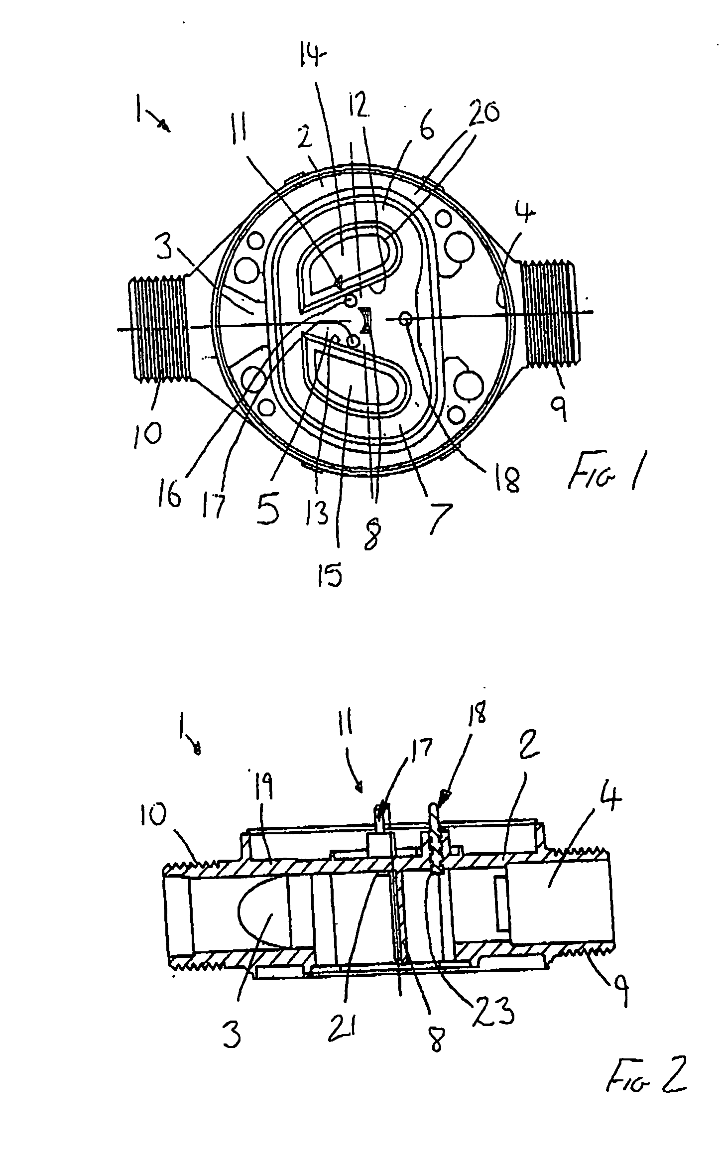
[0008] This arrangement of the electrodes is particularly advantageous as the sensitivity of the detector means is improved without adversely affecting the calibration and stability of the oscillator as a fluid measuring device. Thus, the positioning of the electrodes such that instead of being flush with the body, they protrude into the flow does not disturb the flow to the extent that accurate measurement is no longer possible and in fact allows particularly accurate metering. Further, it has been found that the electrode arrangement of the invention minimises false readings caused by mechanical vibration or water pressure pulsation.
[0009] In another embodiment, at least one of the pair of sensing electrodes protrudes from the body into the flow a distance between 0.5 mm and 10 mm. This range of protrusion improves the accuracy of the meter while not creating a significant blockage in the flow path, which would result in a pressure drop that may disturb the oscillations and therefore the accuracy.
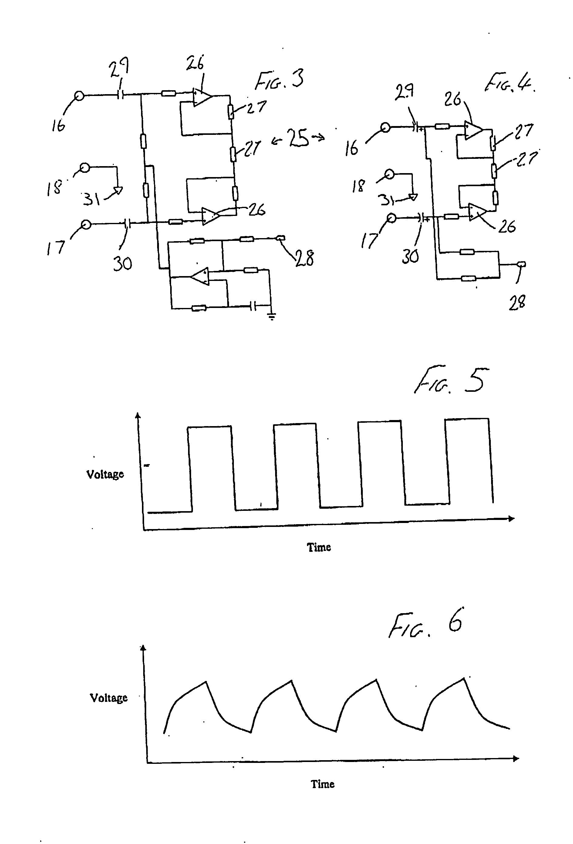
[0016] The use of a driving signal and, in particular, an alternating driving signal is advantageous as the detector means and therefore the metering of fluid flow is accurate and reliable.

Problems solved by technology

However, in practice, it can be particularly difficult to obtain accurate measurements (i.e. within one or two percent) in situations where the flow rate can vary over a wide range, and where the pressure of the fluid may vary substantially.
Further, water may be caused to move inside the oscillator by other external effects such as mechanical vibration or water pressure pulsation although there is no net flow of water.

Method used


Image

  • Meter
  • Meter
  • Meter

Examples


Embodiment Construction

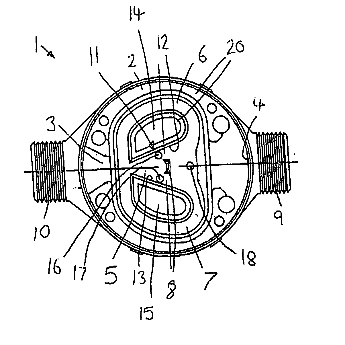
[0027] A fluidic oscillator 1 is shown in FIG. 1 and is generally of known kind and is for use as a domestic water meter. The oscillator meter 1 comprises a body 2, which includes walls 20 that define a plurality of flow paths. The body 2 defines an inlet portion 3, an outlet portion 4 and a main channel 5 therebetween. The body 2 also defines feedback means, which comprises two looped feedback channels 6, 7, that split from the main channel 5 and then lead back to rejoin the main channel 5 adjacent the inlet portion 2. The splitter 8 is located centrally in the main channel 5, between the splitting and rejoin points of the feedback channels 6, 7.

[0028] The inlet portion 3 comprises a narrowed aperture that receives flow from an inlet tube (not shown) that is connected to the inlet portion 3 by a screw thread 10. Similarly, the outlet portion 4 is adapted to receive an outlet tube (not shown) that is connected thereto by a screw thread 9.

[0029] Fluid received through the inlet por...


PUM


Abstract

A fluidic oscillator liquid flow meter comprising a body having an inlet portion to receive a flow of liquid to be measured, an outlet portion, a main channel defining a flow path between the inlet and outlet, the flow path including feedback means to induce oscillations in the flowing fluid, the oscillations being detected by detector means comprising means to apply a magnetic field across the flow path and sensing electrodes to detect the resulting e.m.f, the electrodes being positioned such that they protrude from the body into the flow path. A meter having driving signal means, which applies an alternating driving signal to the sensing electrodes is also disclosed.

Description

PRIORITY CLAIM [0001] This application claims the benefit of U.S. Provisional Application No. 60 / 677,960, filed May 5, 2005 and Great Britain Patent Application No. 0508342.3, filed Apr. 26, 2005.FIELD OF THE INVENTION [0002] This invention relates to a fluid flow meter and in particular to a meter for measuring the flow of liquids and operating on the fluidic oscillator principle. BACKGROUND [0003] It is well known that the frequency of oscillation of a fluidic oscillator is dependent (though not necessarily linearly) on the rate of flow through it. This principle has been used for the measurement of the flow of liquids and in particular in water meters to measure the water consumption of a property, for example. However, in practice, it can be particularly difficult to obtain accurate measurements (i.e. within one or two percent) in situations where the flow rate can vary over a wide range, and where the pressure of the fluid may vary substantially. Accuracy of measurement needs t...

Claims


Application Information

Patent Timeline
IPC IPC(8): G01F1/20
CPCG01F1/3227G01F1/58G01F1/3245G01F1/325
Inventor FAIRMAN, MARK ANDREWCOTTAM, DAVID
Owner SEVERN TRENT METERING SERVICES
Learn More