Flow sensor with double obstruction

Active Publication Date: 2009-03-12
INTERMED EQUIPAMENTO MEDICO HOSPITALAR
View PDF8 Cites 22 Cited by
  • Summary
  • Abstract
  • Description
  • Claims
  • Application Information

AI Technical Summary

Benefits of technology

[0025]More particularly, an object of the present invention is to provide the combination of both fixed and variable obstructions in one single body, resulting in a flow sensor with double obstruction, with the result of improving sensitivity and stability aspects, especially in cases of continuous monitoring.
[0026]In a preferential configuration, the fixed obstruction comprises a rigid plate with a semi-ring orifice, defining a centered disc which is fixed by the top through a section which is aligned to pressure ports, assembled crosswise at the passage o

Problems solved by technology

However, these sensors make use of a screen as an obstruction element, liable to the accumulation of patient secretions, making this kind of sensor inadequate to continuously monitor the patient.
Furthermore, they are relatively large and heavy.
Despite attempting to solve the problems of the Fleisch pneumotachograph, the sensor as disclosed by the U.S. Pat. No. 4,047,521 shows non-linear response, since the pressure drop is a square function of flow, thus resulting in low sensitivity at low flows and high resistance at higher flows.
Also in this configuration, the sensitivity to low flows constitutes the main problem.
Furthermore, geometry as proposed does not avoid the accumulation of secretions along the obstruction.
That sensor also presents quadratic relationship between pressure and flow, thus resulting in low sensitivity under low flow.
This alternative requires extreme care for handling, cleaning and sterilization, due to the fragile flexible flaps, usually constructed from

Method used


Image

  • Flow sensor with double obstruction
  • Flow sensor with double obstruction
  • Flow sensor with double obstruction

Examples


Example

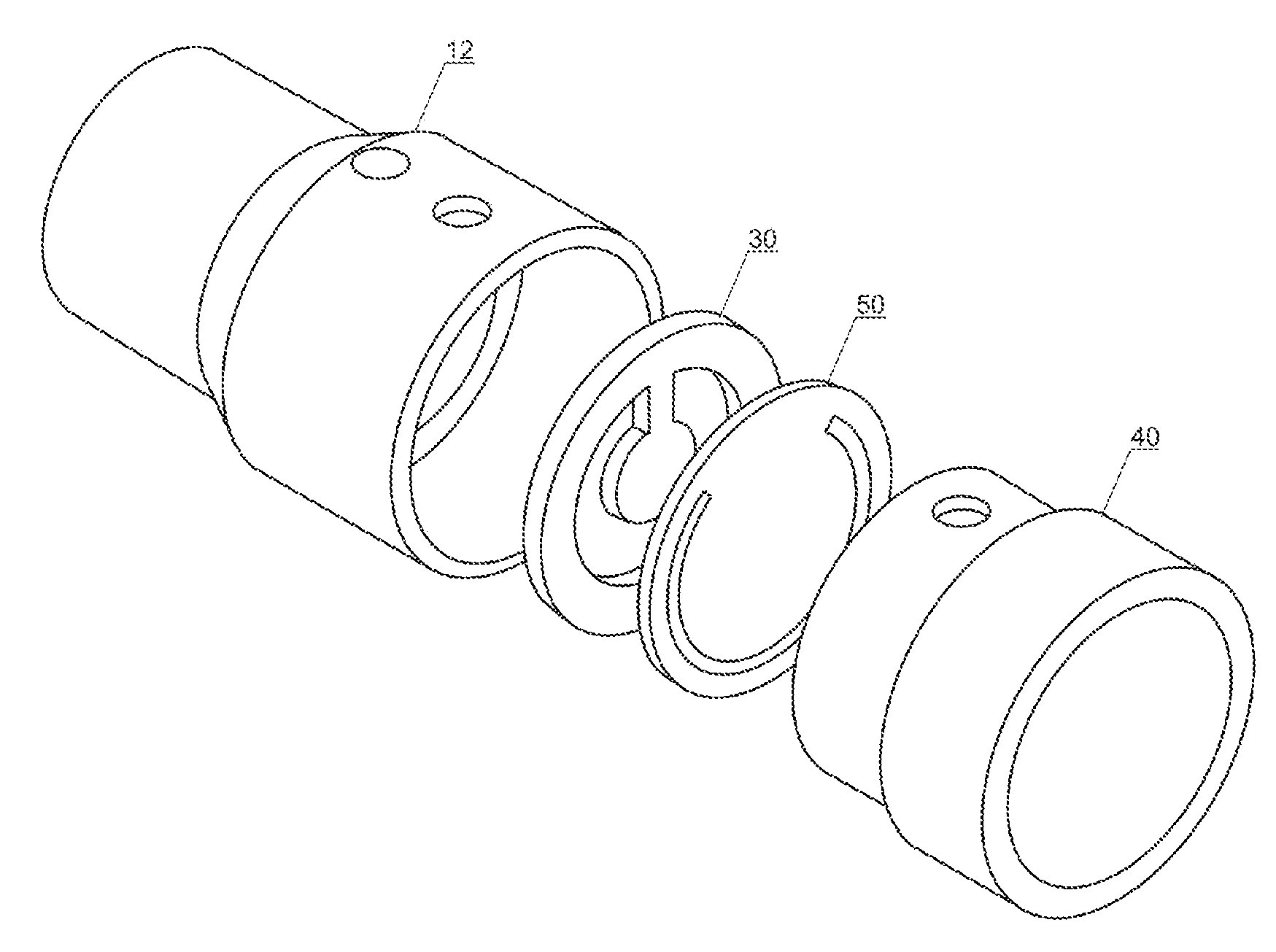
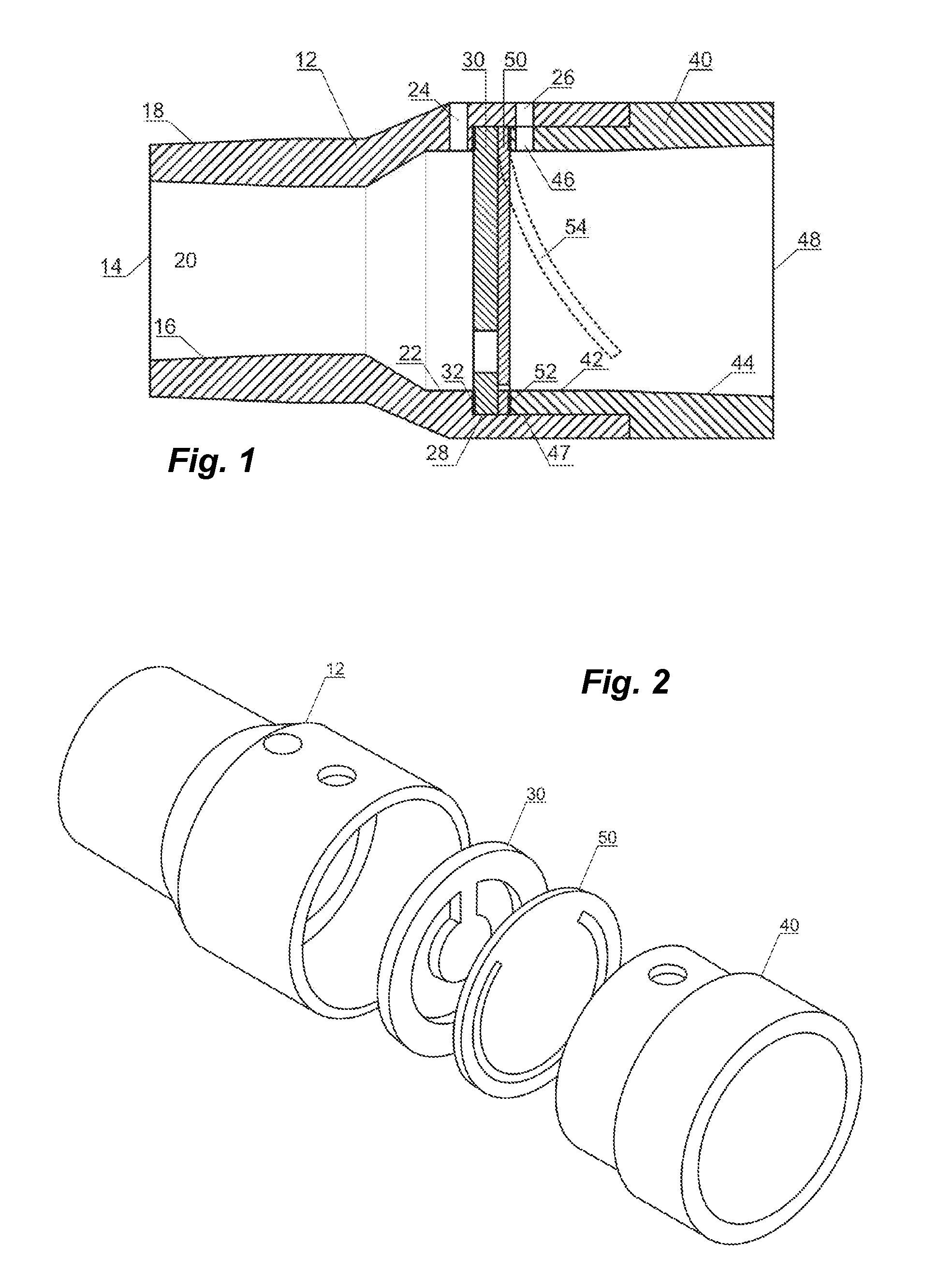
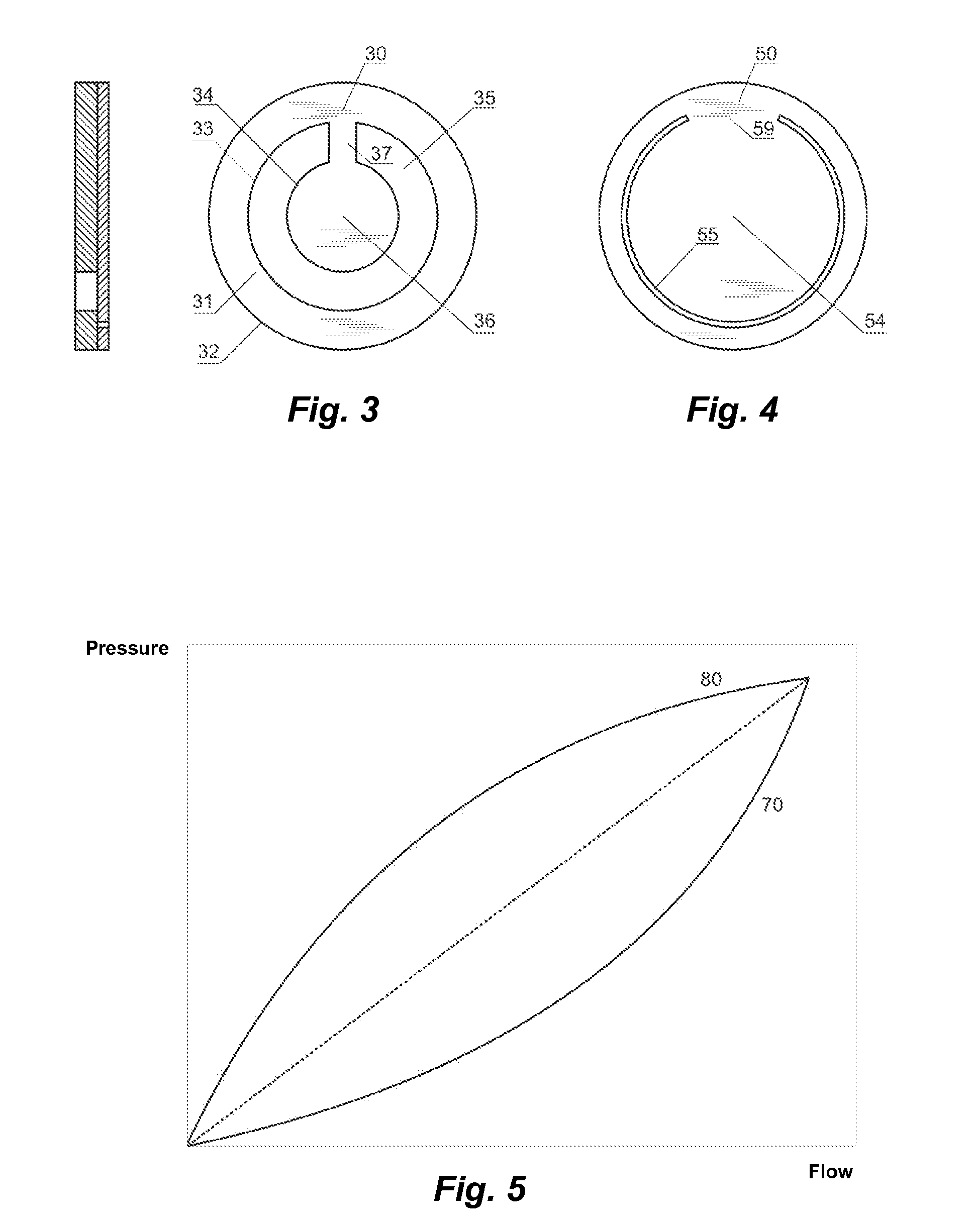
[0037]Referring to FIG. 1, the double obstruction sensor of the present invention, in a preferential embodiment, comprises a front part 12 of a main body having an inlet port 14 with internal diameter 16, thus defining the initial portion of the flow tube 20 and external diameter 18 defining the outside of the body. Both diameters 16 and 18, are preferably in agreement with applicable connection standards, i.e. conic connectors with 15 mm and 22 mm diameters according to the ISO rule 5356-1, Anesthetic and Respiratory Equipment—Conical Connectors. The initial portion of the flow tube 20 is prolonged and widened up to the diameter 22 and subsequently with longer diameter 28, where the first fixed obstruction element 30 is assembled crosswise and subsequently the second variable obstruction element 50 downstream.

[0038]The front part 12 of the main body includes two ports for pressure measurement—the first port 24 located upstream from the fixed obstruction element 30 and the second po...


PUM


Abstract

The present invention refers to a flow sensor with double obstruction disclosing a simple and innovative structure, able to promote a series of advantages and new technical effects from the combination of fixed and variable obstruction elements. More particularly, the present invention comprises a front main body (12) and a main body (40) fitted to each other so to press two obstruction elements, the first one being fixed (30) and the second being variable (50), so to increase sensitivity and reduce the annoying noise, being especially useful to monitor patients for long periods.

Description

FIELD OF THE INVENTION[0001]The present invention relates to a flow sensor with double obstruction, and also relates to a sensor comprising a body defining a flow passage, a first fixed obstruction mounted crosswise to the flow passage, a second obstruction, also mounted crosswise to the flow passage and downstream from the first fixed obstruction and two ports for pressure measurement located upstream from the fixed obstruction and downstream from the variable obstruction.[0002]The present invention also relates to a sensor with double obstruction combining fixed and variable obstructions in one single body, to obtain better sensitivity and less noise, especially for the monitoring of patients for long periods.[0003]The sensor object of the present invention relates to the field of flow sensors of the type generating pressure drop that is proportional to the flow passing through the sensor, due to an obstruction interposed at the flow passage.BACKGROUND OF THE INVENTION[0004]These ...

Claims


Application Information

Patent Timeline
IPC IPC(8): G01F1/42
CPCG01F1/42G01F1/40
Inventor BONASSA, JORGE
Owner INTERMED EQUIPAMENTO MEDICO HOSPITALAR
Why Eureka
Try Eureka