Dual-fuel injector

Active Publication Date: 2020-04-07
L'ORANGE GMBH
View PDF20 Cites 0 Cited by
  • Summary
  • Abstract
  • Description
  • Claims
  • Application Information

AI Technical Summary

Benefits of technology

[0004]Taking this as a starting point, it is the underlying object of the invention t

Problems solved by technology

This is disadvant

Method used


Image

  • Dual-fuel injector

Examples


Embodiment Construction

[0026]In the following description and the drawings, elements with the same or a comparable function correspond to the same reference signs.

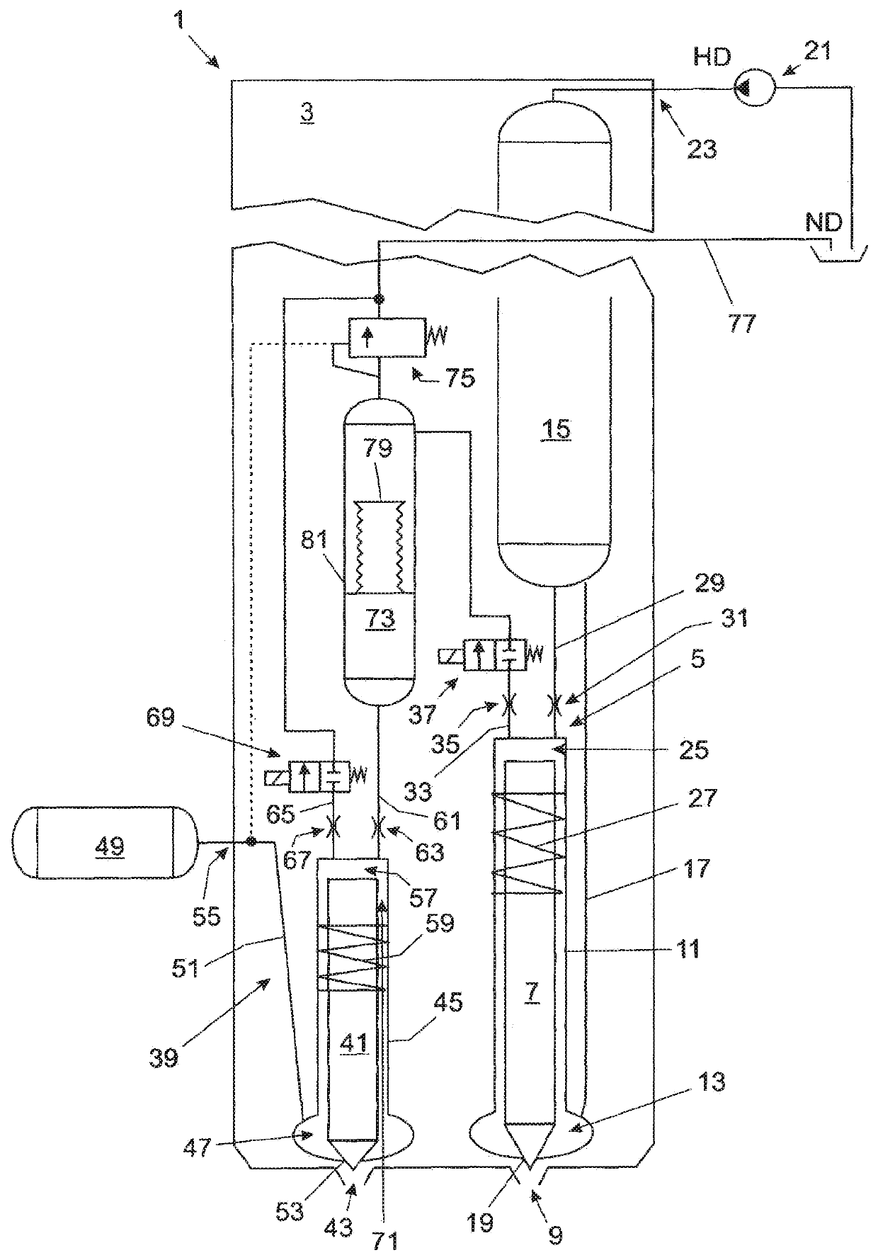
[0027]FIG. 1 shows a dual-fuel injector 1 (two-substance nozzle or two-substance injector) according to the invention for a fuel injection device of a combustion engine (internal combustion engine), preferably for a gas common rail system. The dual-fuel injector 1 is provided for the injection mode with a first, liquid fuel (particularly diesel fuel) and a second, gaseous fuel (combustion gas), i.e. both for a single fuel mode with liquid fuel and a dual fuel mode with combustion gas and a liquid fuel ignition jet.

[0028]The dual-fuel injector 1 has—in an injector housing 3—a liquid fuel injector unit 5 with a nozzle needle 7, which is assigned to a liquid fuel nozzle arrangement 9 of the dual-fuel injector 1. The nozzle needle 7 is accommodated in an axial bore 11 of the liquid fuel injector unit 5, which is simultaneously provided as a guide fo...


PUM


Abstract

A dual-fuel injector for a fuel injection device, including: a liquid fuel injector unit with a nozzle needle assigned to a liquid fuel nozzle arrangement of the dual-fuel injector and which is stroke controllable via a first control chamber; and a gas injector unit with a gas nozzle needle assigned to a gas nozzle arrangement of the dual-fuel injector and which is stroke controllable via a second control chamber. Each of the control chambers can be impinged with a control fluid to control the stroke of the respective nozzle needle. The control fluid from both the control chambers can be discharged. The dual-fuel injector has a control fluid reservoir in which discharged control fluid from the first control chamber can be introduced; the dual-fuel injector is configured to impinge the second control chamber with control fluid from the control fluid reservoir for the stroke control of the gas nozzle needle.

Description

[0001]The present application is a 371 of International application PCT / EP2014 / 003046, filed Nov. 13, 2014, which claims priority of DE 10 2013 021 810.1, filed Dec. 20, 2013, the priority of these applications is hereby claimed and these applications are incorporated herein by reference.BACKGROUND OF THE INVENTION[0002]The present invention relates to a dual-fuel injector for a fuel injection device, in particular a combustion engine, in accordance with the preamble of claim 1. In particular, the dual-fuel injector can be used with ignition jet engines, which, in addition to an ignition jet mode using combustion gas (and a liquid fuel ignition jet), provide a pure liquid fuel mode. Diesel fuel, heavy oil or bio oil can be provided as a liquid fuel, for example.[0003]In dual-fuel injectors of the type in question, which use liquid fuel for (indirect) control of the gas injector unit (the principle being pilot valve—actuator—control chamber), especially those which make use of high-p...

Claims


Application Information

Patent Timeline
IPC IPC(8): F02M43/04F02M47/02F02M45/08F02M63/00F02M55/00F02D19/06F02D19/10
CPCF02M55/002F02D19/0694F02D19/10F02M43/04F02M47/027F02M45/086F02M63/0045Y02T10/36F02M2200/40Y02T10/30
Inventor KALENBORN, MARKUS
Owner L'ORANGE GMBH
Why Eureka
Try Eureka