Silicon composite negative electrode material and preparation method therefor, and lithium ion battery

Pending Publication Date: 2022-04-07
BTR NEW MATERIAL GRP CO LTD +1
0 Cites 0 Cited by

AI-Extracted Technical Summary

Problems solved by technology

Conventional graphite-based negative electrode materials are commonly used for mobile phones, notebook computers, digital cameras, electric tools and the like, and their capacity for storing lithium ions is relatively low (theoretically 372 mAh/g), which leads to the problem of low overall capacity of batteries manufactured thereby.
Currently, the global automobile industry transitions from internal combustion engine to electric automobile, and therefore the requirements for battery energy density are also getting higher and higher, so that the lithium ion battery made of the conventional graphite-based negative electrode material cannot meet the requirements of the electric automobiles.
However, because silicon undergoes large-volume expansion (up to 300%) in charge and discharge cycles, negative electrode cracking and pulverization are caused, which limits its commercial application.
Although silicon monoxide can alle...

Benefits of technology

[0065](1) In the preparation method provided in the present disclosure, by controlling the condensation temperature within a specific range, the uniformity of the element distribution in the silicon composite negative electrode material is significantly improved, and the compactness of the condensed depo...

Abstract

Provided are a silicon composite negative electrode material and a preparation method therefor, and a lithium ion battery. The silicon composite negative electrode material comprises silicon composite particles and a carbon coating layer, wherein the carbon coating layer is coated on at least part of the surface of the silicon composite particle; and the silicon composite particle comprises silicon, a silicon oxide SiOx and a silicate containing the metal element M, wherein 0<x<2. The method comprises: condensing a silicon source vapor and a vapor containing the metal element M at 700-900° C. under a vacuum to obtain a silicon composite, the silicon composite comprising a silicon oxide SiOx and a silicate, wherein 0<x<2; and post-processing the silicon composite to obtain a silicon composite negative electrode material.

Application Domain

Magnesium silicatesSilica +3

Technology Topic

Carbon coatingComposite material +6

Image

  • Silicon composite negative electrode material and preparation method therefor, and lithium ion battery
  • Silicon composite negative electrode material and preparation method therefor, and lithium ion battery
  • Silicon composite negative electrode material and preparation method therefor, and lithium ion battery

Examples

  • Experimental program(6)

Example

Example 1
[0123]A silicon composite negative electrode material was prepared according to the following method in the present disclosure:
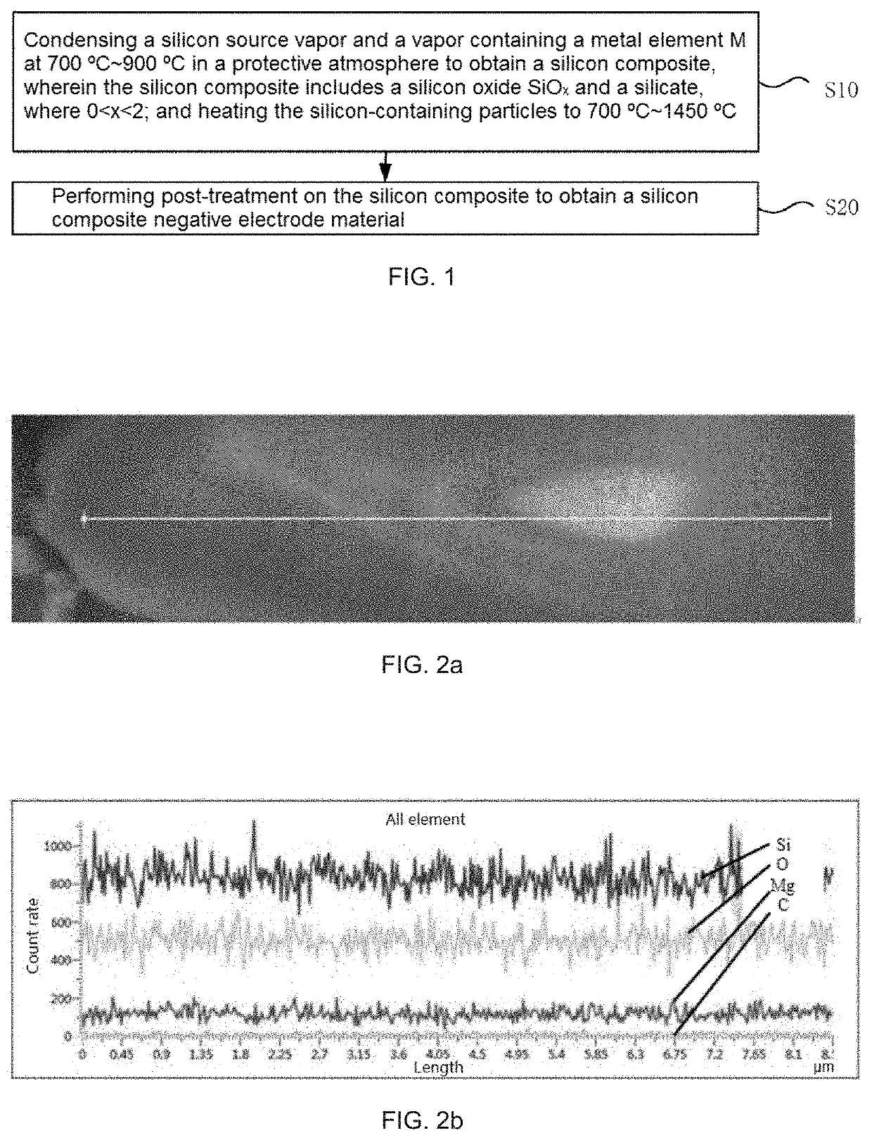
[0124](1) mixing 5 kg of a silicon powder (D50 was 10 μm) and 10 kg of a silicon micro powder (D50 was 5 μm) with a VC mixer for 30 min to obtain an SiO raw material, and placing the same at an end of a reaction chamber of a vacuum furnace close to a furnace tail;
[0125](2) placing 2 kg of a magnesium powder at an end of the reaction chamber of the vacuum furnace close to a furnace opening;
[0126](3) arranging a collector in a condensation chamber, and heating to 1300° C. under a vacuum condition of 200 Pa to generate an SiO vapor and an Mg vapor in the furnace;
[0127](4) controlling the temperature of the condensation chamber to be 800° C., cooling a uniformly mixed gaseous mixture in the condensation chamber for 12 h to obtain a silicon composite, and after the reaction was finished, cooling the equipment and collecting a product 11 kg;
[0128](5) making 5 kg of the product in step (4) subjected to processes such as crushing, ball milling, and classification to control a particle size (D50) thereof at 4 μm;
[0129](6) placing the above 4 μm silicon composite in a CVD furnace, introducing a nitrogen gas through an outer path as a protective gas, introducing a methane gas through an inner path as a carbon source, and heating to 950° C. to decompose methane, wherein a nitrogen flow rate was set as 3.5 L/min in the reaction, and 5% carbon was coated on a surface of the negative electrode material; and
[0130](7) after completing the coating, placing the obtained material in a roller kiln to undergo high temperature carbonization at 960° C., to obtain a stable silicon composite negative electrode material.
[0131]The finally prepared silicon composite negative electrode material particles were cut using a Hitachi E-3500 ion miller, a topographic structure of a section thereof was observed on a Hitachi S-4800 cold-field emission scanning electron microscope, and the elemental composition and distribution thereof were observed using an Oxford energy dispersive spectrometer, UK.
[0132]FIG. 2a is a scanning electron microscopic picture of the silicon composite negative electrode material prepared in the present example; and FIG. 2b is an element distribution map of a particle section marked in FIG. 2a. In FIG. 2b, the distribution curves of elements Si, O, and Mg are parallel wave lines. It may be seen from FIG. 2a and FIG. 2b that at any position of the material particles, all of the contents of the three elements Si, O, and Mg are kept at a constant level, and the element distribution uniformity is quite good.
[0133]The silicon composite negative electrode material prepared in the present example includes silicon, silicon oxide, and magnesium silicate, the chemical formula of the silicon oxide is SiOx (x=0.63), and the surface and voids of the silicon composite negative electrode material further contain carbon. The silicon composite negative electrode material has an average particle size of 5.5 μm, and a specific surface area of 2 m2/g. In the silicon composite negative electrode material, a mass fraction of oxygen element is 26%, a mass fraction of magnesium element is 8%, and a mass fraction of carbon element is 5%.
[0134]See Table 1 for the performance characterization results of the silicon composite negative electrode material prepared in the present example.

Example

Example 2
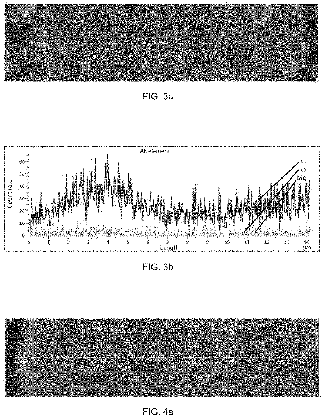
[0135]The present example is merely different from Example 1 in that in step (4), the temperature of the condensation chamber is controlled to be 700° C. The other operations for preparing the silicon composite negative electrode material are the same as those in Example 1.
[0136]The silicon composite negative electrode material prepared in the present example includes silicon, silicon oxide, and magnesium silicate, the chemical formula of the silicon oxide is SiOx (x=0.63), and the surface and voids of the silicon composite negative electrode material further contain carbon. The silicon composite negative electrode material has an average particle size of 5.5 μm, and a specific surface area of 3.5 m2/g. In the silicon composite negative electrode material, a mass fraction of oxygen element is 26%, a mass fraction of magnesium element is 8%, and a mass fraction of carbon element is 5%.
[0137]The silicon composite negative electrode material prepared in the present example was subjected to particle section line scanning using an energy dispersive spectrometer in combination with a scanning electron microscope, and results thereof are similar to those in Example 1, wherein the distribution curves of elements Si, O, and Mg are parallel wave lines, indicating that at any position of the material particles, the contents of the three elements Si, O, and Mg are kept at a constant level, and the element distribution uniformity is quite good.

Example

Example 3
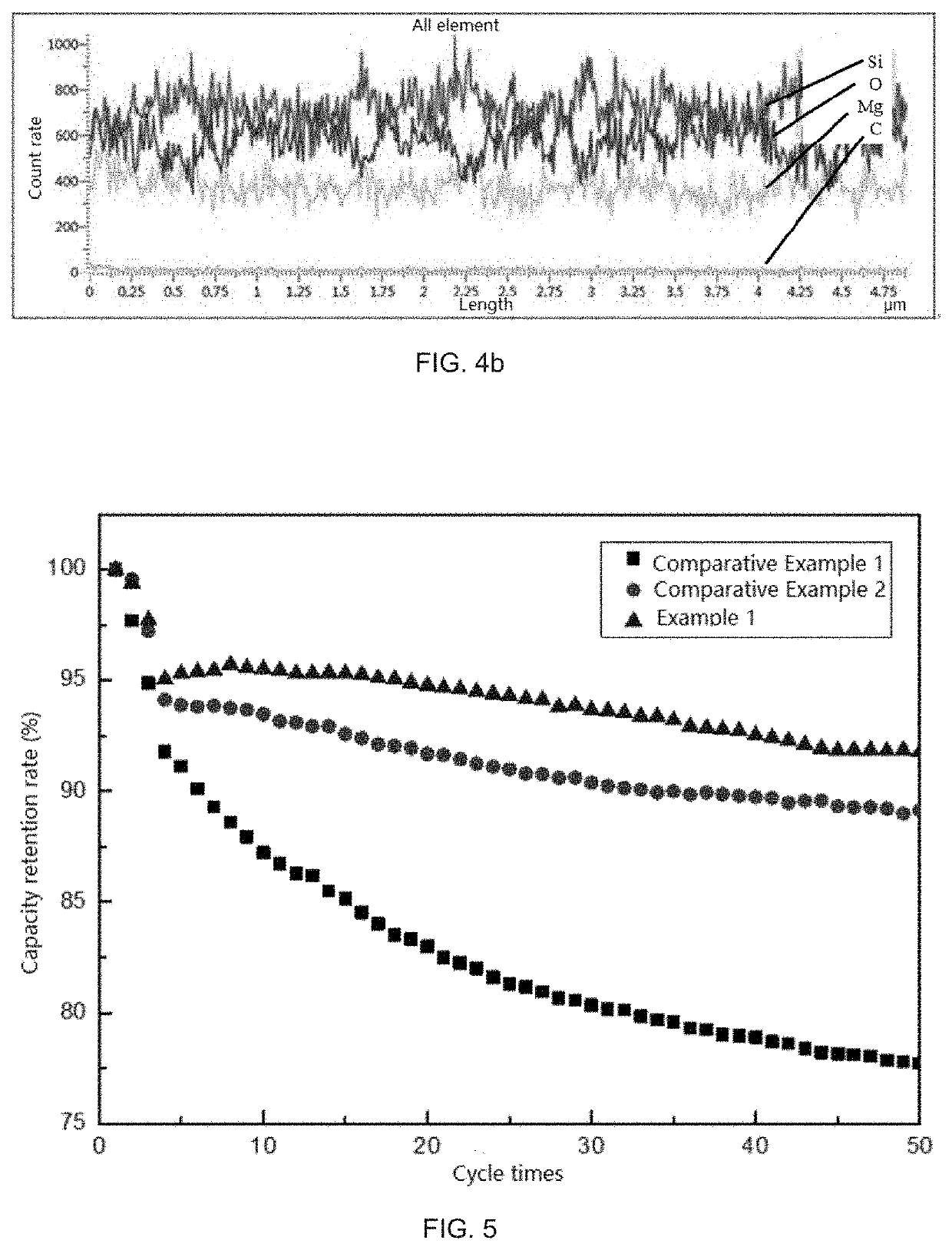
[0138]The present example is merely different from Example 1 in that in step (4), the temperature of the condensation chamber is controlled to be 850° C. The other operations for preparing the silicon composite negative electrode material are the same as those in Example 1.
[0139]The silicon composite negative electrode material prepared in the present example includes silicon, silicon oxide, and magnesium silicate, the chemical formula of the silicon oxide is SiOx (x=0.63), and the surface and voids of the silicon composite negative electrode material further contain carbon. The silicon composite negative electrode material has an average particle size of 5.5 μm, and a specific surface area of 3 m2/g. In the silicon composite negative electrode material, a mass fraction of oxygen element is 26%, a mass fraction of magnesium element is 8%, and a mass fraction of carbon element is 5%.
[0140]The silicon composite negative electrode material prepared in the present example was subjected to particle section line scanning using an energy dispersive spectrometer in combination with a scanning electron microscope, and results thereof are similar to those in Example 1, wherein the distribution curves of elements Si, O, and Mg are parallel wave lines, indicating that at any position of the material particles, the contents of the three elements Si, O, and Mg are kept at a constant level, and the element distribution uniformity is quite good.

PUM

no PUM

Description & Claims & Application Information

We can also present the details of the Description, Claims and Application information to help users get a comprehensive understanding of the technical details of the patent, such as background art, summary of invention, brief description of drawings, description of embodiments, and other original content. On the other hand, users can also determine the specific scope of protection of the technology through the list of claims; as well as understand the changes in the life cycle of the technology with the presentation of the patent timeline. Login to view more.

Similar technology patents

Method for preparing hard alloy in vacuum extrusion mode

Owner:河源富马硬质合金股份有限公司

Marbled ceramic glaze

Owner:NANNING SHENGRUN TECH

Classification and recommendation of technical efficacy words

  • avoid occurrence
  • good compactness

Liquid crystal display panel and driving method therefor

ActiveUS20050083279A1avoid occurrence
Owner:HANNSTAR DISPLAY CORPORATION

Lighting power supply device and method for controlling holding current

ActiveUS20120104970A1avoid occurrence
Owner:MITSUMI ELECTRIC CO LTD

Antenna diversity receiver

InactiveUS6931081B2effectively suppressavoid occurrence
Owner:CONTINENTAL AUTOMOTIVE GMBH

Cordless telephone system

InactiveUS20010053139A1avoid occurrencequality deterioration
Owner:UNWIRED PLANET
Why Eureka
Try Eureka