
Ratcheting torque wrench

a torque wrench and torque technology, applied in the field of ratcheting torque wrenches, can solve the problems of limiting surgeon visibility, limiting surgeon visibility, and rarely getting the optimal handle alignment for torque application,

Active Publication Date: 2006-11-23
CUSTOM SPINE INC
View PDF6 Cites 40 Cited by
  • Summary
  • Abstract
  • Description
  • Claims
  • Application Information

AI Technical Summary

Benefits of technology

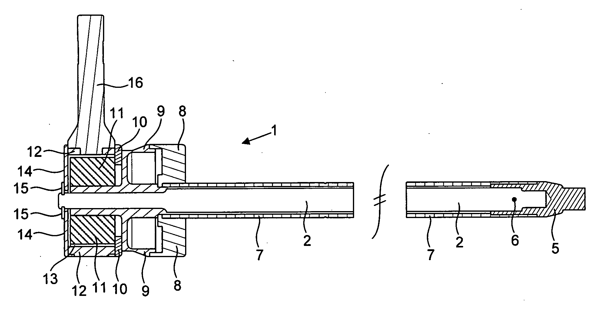
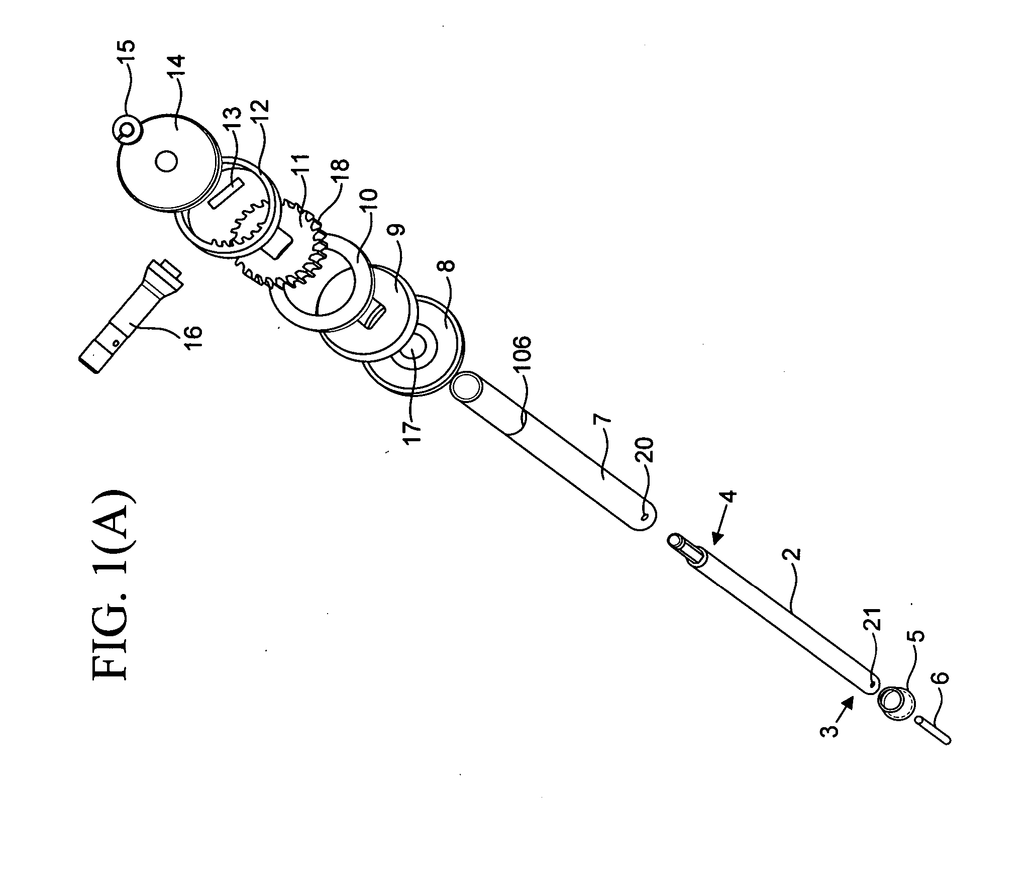
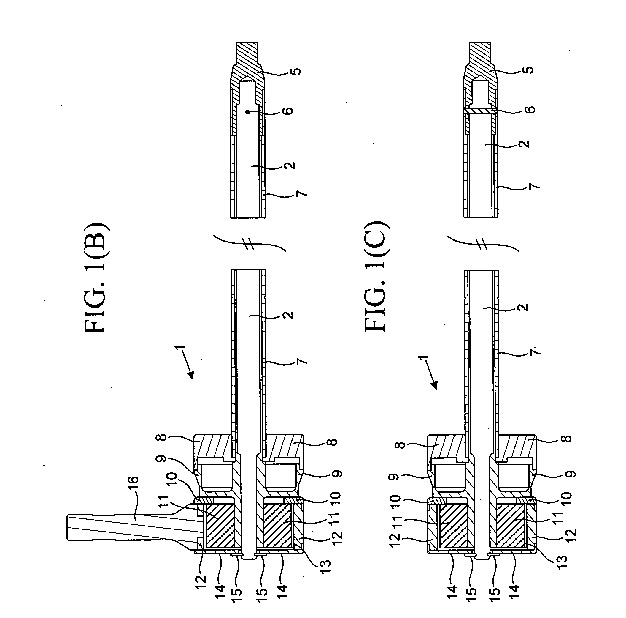
"The patent text describes a ratcheting torque wrench that is used to tighten locking elements in orthopedic implants. The wrench includes a torsional shaft, a hex tip, a dowel pin, a sleeve, a sleeve dial, a shaft dial, a ratchet housing, a nylon ring, a ratchet gear, a ratchet cover, a retaining ring, a ratchet fitting, and a ratchet cover. The ratchet gear is connected to the ratchet housing and can be engaged with a handle. The assembly also includes a counter-torque wrench and a ratchet cover. The technical effects of this invention include improved torque control, reduced damage to the implant, and improved ease of use."

Problems solved by technology

Because the orientation of the hex is generally always random, the surgeon rarely gets the optimal handle alignment to apply the needed torque to safely conduct the final tightening of the spinal construct.
Most conventional torque wrenches have shortcomings such as: (1) a break away design that allows for a violent sudden motion in order to function, which effects the calibration after multiple usages; (2) limited leverage requires a two-handed operation that leads to having an assistant applying counter-torque force using a counter-torque instrument; (3) too bulky therefore limiting surgeon visibility; and (4) random orientation leading to less than optimal ergonomics for torque application.

Method used


Image

  • Ratcheting torque wrench
  • Ratcheting torque wrench
  • Ratcheting torque wrench

Examples


Embodiment Construction

[0033] The embodiments herein and the various features and advantageous details thereof are explained more fully with reference to the non-limiting embodiments that are illustrated in the accompanying drawings and detailed in the following description. Descriptions of well-known components and processing techniques are omitted so as to not unnecessarily obscure the embodiments herein. The examples used herein are intended merely to facilitate an understanding of ways in which the embodiments herein may be practiced and to further enable those of skill in the art to practice the embodiments herein. Accordingly, the examples should not be construed as limiting the scope of the embodiments herein.

[0034] As mentioned, there remains a need for a novel torque wrench where the optimal alignment is always guaranteed and which generally overcomes the limitations of the conventional torque wrenches. The embodiments herein achieve this by providing a ratcheting torque wrench that provides opt...


PUM

PropertyMeasurementUnit
ratcheting torqueaaaaaaaaaa
diameteraaaaaaaaaa
torqueaaaaaaaaaa

Abstract

A ratcheting torque wrench comprising a torsional shaft connected to a hex tip; a sleeve that fits over the torsional shaft; a sleeve dial having a hole and configured to fit around the sleeve such that the diameter of the sleeve dial hole accommodates the sleeve; a shaft dial connected to the sleeve dial; a nylon ring connected to a ratchet housing; a ratchet gear connected to the ratchet housing, the ratchet housing mating with the ratchet gear; a spring connected to the nylon ring and the ratchet gear; a ratchet cover that fits over the ratchet housing; a retaining ring connected to the ratchet cover and configured to engage the torsional shaft; a ratchet fitting connected to the ratchet housing, wherein the ratchet fitting accommodates a first handle, wherein the sleeve has a hole to accommodate a second handle.

Description

CROSS-REFERENCE TO RELATED APPLICATION [0001] This application claims the benefit of U.S. Provisional Patent Application No. 60 / 683,746 filed on May 23, 2005, the contents of which, in its entirety, is herein incorporated by reference.BACKGROUND [0002] 1. Field of the Invention [0003] The embodiments herein generally relate to medical devices, and, more particularly, to medical devices used for spinal surgeries. [0004] 2. Description of the Related Art [0005] Most conventional torque wrenches typically have a hex tip at the bottom and a T-handle at the other end of the instrument. Because the orientation of the hex is generally always random, the surgeon rarely gets the optimal handle alignment to apply the needed torque to safely conduct the final tightening of the spinal construct. Most conventional torque wrenches have shortcomings such as: (1) a break away design that allows for a violent sudden motion in order to function, which effects the calibration after multiple usages; (2...

Claims


Application Information

Patent Timeline
Patent Type & Authority Applications(United States)
IPC IPC(8): B25B13/46B25B23/14
CPCA61B17/7001A61B17/8875Y10T408/63B25B13/463B25B13/462
Inventor ABDELGANY, MAHMOUD F.
Owner CUSTOM SPINE INC
Learn More