Adaptable user interface for diagnostic imaging

a diagnostic imaging and user interface technology, applied in the field of scanning and analyzing imaging data in medical systems, can solve the problems of increasing the skills required of operators, imaging system not providing patient history, genetic makeup, other relevant patient information to the radiologist,

Inactive Publication Date: 2006-11-23
GENERAL ELECTRIC CO
View PDF9 Cites 34 Cited by
  • Summary
  • Abstract
  • Description
  • Claims
  • Application Information

AI Technical Summary

Benefits of technology

[0005] In one embodiment, a method for operating a plurality of user interfaces coupled to a plurality of medical devices through a communication network includes performing medical diagnostics on a patient using at least two of the plurality of medical devices, wherein the user interface is configured to control the at least two of the plurality of medical devices, and displaying a result of the medical diagnostics on a

Problems solved by technology

As medical imaging technology advances, the skills required of an operator become increasingly demanding.
During planning and diagnosis of a medical imaging procedure, the imaging system does not provide patient history, genetic makeup, and other relevant patient information to the radiologist.
Nor

Method used


Image

  • Adaptable user interface for diagnostic imaging
  • Adaptable user interface for diagnostic imaging
  • Adaptable user interface for diagnostic imaging

Examples


Embodiment Construction

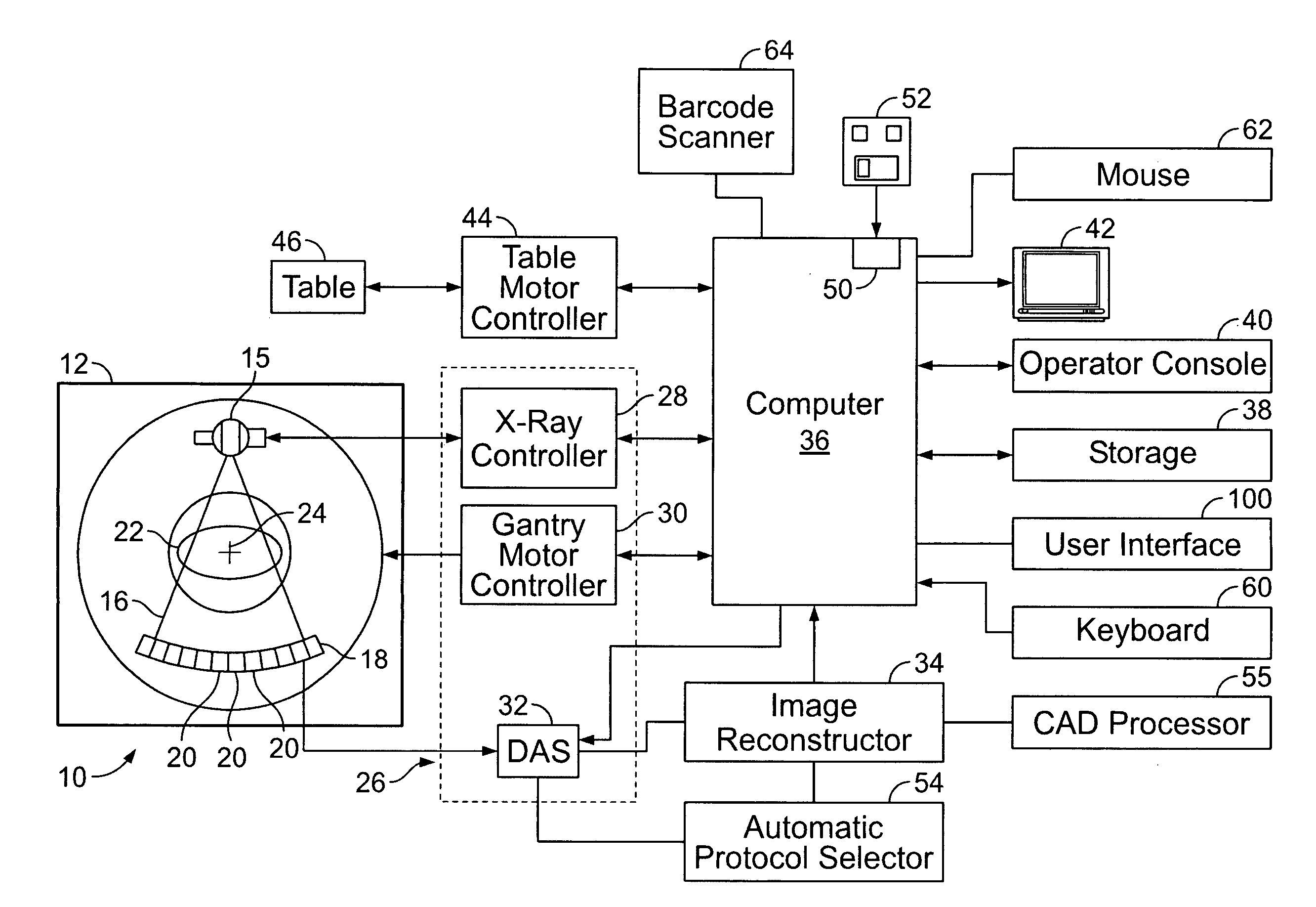
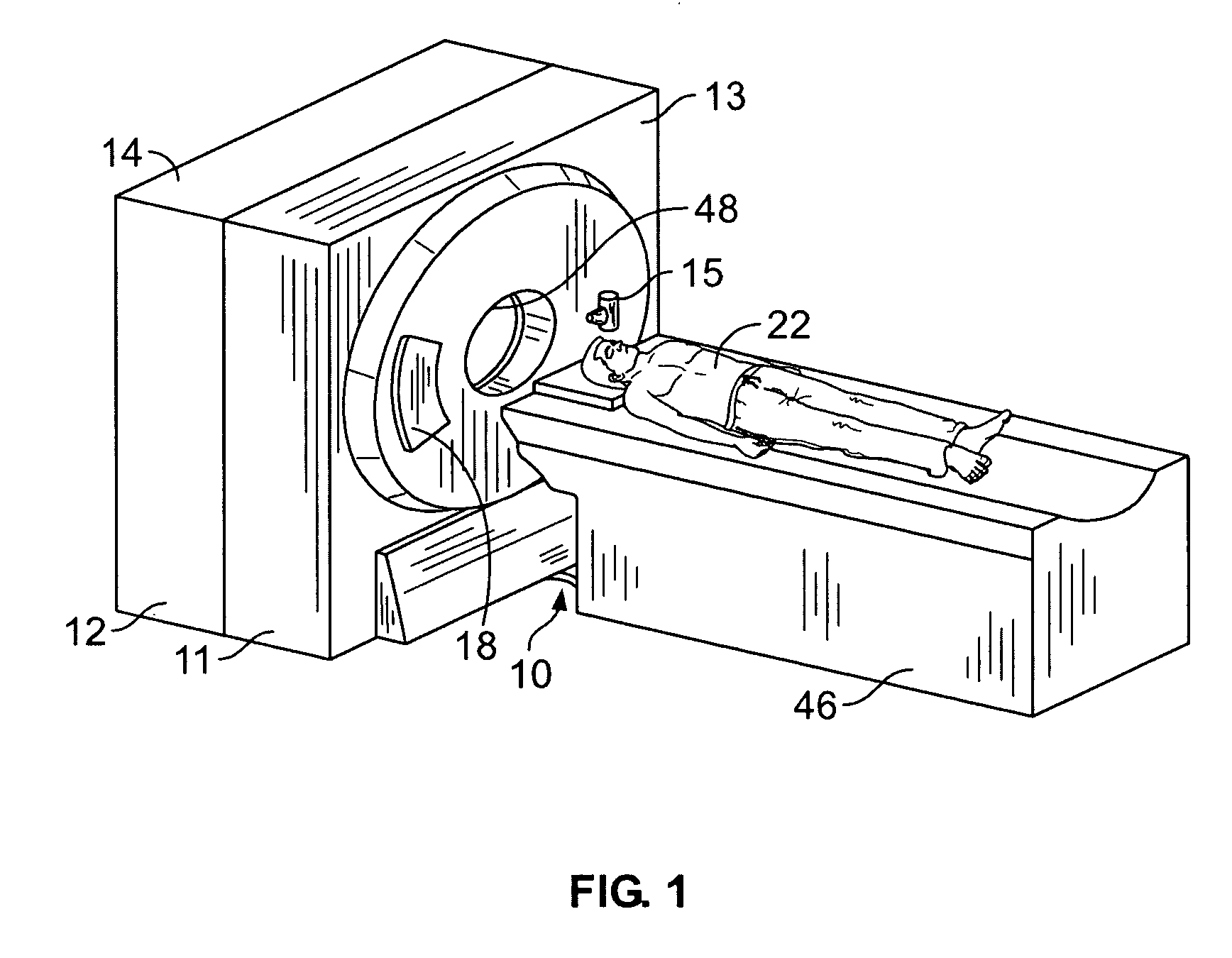
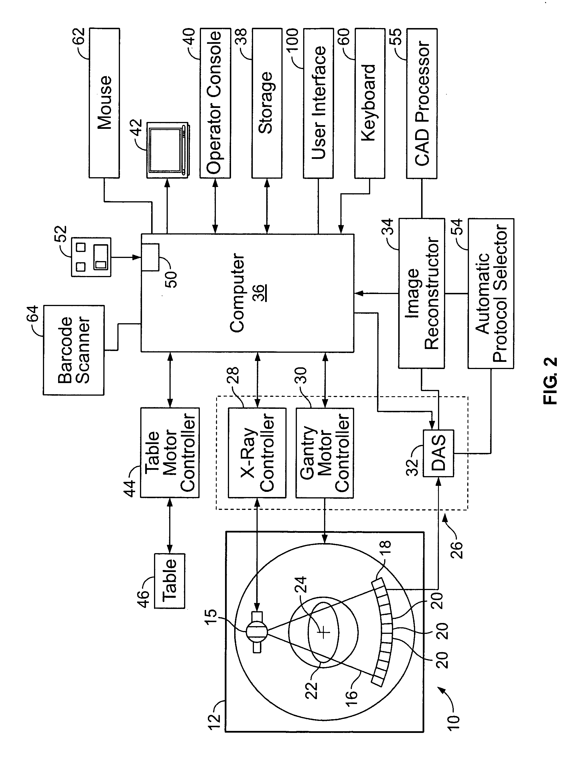
[0018]FIG. 1 is a perspective view of an exemplary imaging system 10. FIG. 2 is a schematic block diagram of imaging system 10 (shown in FIG. 1). In the exemplary embodiment, imaging system 10 is a multi-modal imaging system and includes a first modality unit 11 and a second modality unit 12. Modality units 11 and 12 enable system 10 to scan an object, for example, a patient, in a first modality using first modality unit 11 and to scan the object in a second modality using second modality unit 12. System 10 allows for multiple scans in different modalities to facilitate an increased diagnostic capability over single modality systems. In one embodiment, multi-modal imaging system 10 is a Computed Tomography / Positron Emission Tomography (CT / PET) imaging system 10. CT / PET system 10 includes a first gantry 13 associated with first modality unit 11 and a second gantry 14 associated with second modality unit 12. In alternative embodiments, modalities other than CT and PET may be employed ...


PUM


Abstract

A method for operating a plurality of user interfaces coupled to a plurality of medical devices through a communication network is provided. The method includes performing medical diagnostics on a patient using at least two of the plurality of medical devices, wherein the user interface is configured to control the at least two of the plurality of medical devices, and displaying a result of the medical diagnostics on at least one of the plurality of user interfaces.

Description

CROSS REFERENCE TO RELATED PATENTS [0001] This application claims the benefit of U.S. provisional application No. 60 / 630,970 filed Nov. 24, 2004, which is herein incorporated in its entirety.BACKGROUND OF THE INVENTION [0002] This invention relates generally to medical systems for scanning and analyzing imaging data of patients. As medical imaging technology advances, the skills required of an operator become increasingly demanding. Scanning is very fast in modern scanners, making image acquisition and analysis more interactive. Scanning may also be conducted by an operator using a number of imaging modality systems. [0003] During planning and diagnosis of a medical imaging procedure, the imaging system does not provide patient history, genetic makeup, and other relevant patient information to the radiologist. Nor does an imaging system provide an automatic analysis and comparison of patients with similar history and a statistical projection of likelihood of proper diagnosis from th...

Claims


Application Information

Patent Timeline
IPC IPC(8): A61B8/00
CPCA61B6/032A61B6/464A61B6/467A61B6/5247A61B6/469A61B6/5235A61B6/468
Inventor WEINER, ALLISON L.SENZIG, ROBERT F.WOLOSCHEK, STEVEMAZUMDAR, AMANTAFIELDS, REGANLONDT, JOHNVASS, MELISSAHOGAN, JOEAVILA, RICKCONRY, ANNE
Owner GENERAL ELECTRIC CO
Why Eureka
Try Eureka